Document Number 900-20571 Rev. A
7
0
MAX.
0
1
2
3
LOAD
VOLTS
LINE
AMPS
LOAD AMPS
SPEED
LOW
HIGH
OUT
IN
ON
RESET
IRIS
FOCUS
ON
START
AUX.
INPUT
OFF
NEUTRAL
MIN.
CAMERA
REEL
POWER
OFF
STOP
HIGH
LOW
NORMAL
VIDEO LEVEL
A.C. VOLTAGE
FREQUENCY
R.S. TECHNICAL SERVICES INC.
Camera Operation
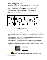
Ensure that the Camera ON/OFF switch is in the
OFF
position before connecting
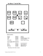
camera to tractor unit, or auxiliary control box to the Controller Power Supply.
Set the LIGHT INTENSITY control to
“MINIMUM”
or full counter clockwise.
Set the REEL SPEED control to the
‘MINIMUM”
or full counter clockwise.
When power is applied to the controller power supply the Frequency and Voltage
indicators will be in the normal range.
Controller Power Supply
1. Camera control on the Controller Power Supply
The adjustable camera power supply provides a nominal 120V DC to the camera, transporter
and other down-hole inspection equipment. This section has video processing circuitry which
extracts the video transmitted by the under ground camera into a NTSC video format. Also
incorporated in to the controller is an audio microphone preamplifier, which provides audio for a
VCR.
The Camera ON/OFF switch controls the camera power supply. Above the switch is a green
LED to indicate that the camera power supply is
on
.
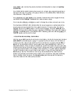
The Camera POWER control knob adjusts the output Voltage of the power supply. Zoom
cameras have a non-adjustable light source. The Camera power only adjusts speed of the
transporter unit. Increase Camera
power
control knob until a red bar appears on the screen.
Decrease Camera
power
knob until red bar just leaves the screen. The transporter speed will
not increase after red bar limit appears on the screen.
Caution:
Do not operate equipment with the over limit red bar on screen.
OVER-VOLTAGE
INDICATOR BAR
SHOWN ON A
MONITOR
SCREEN


