Instruction Manual
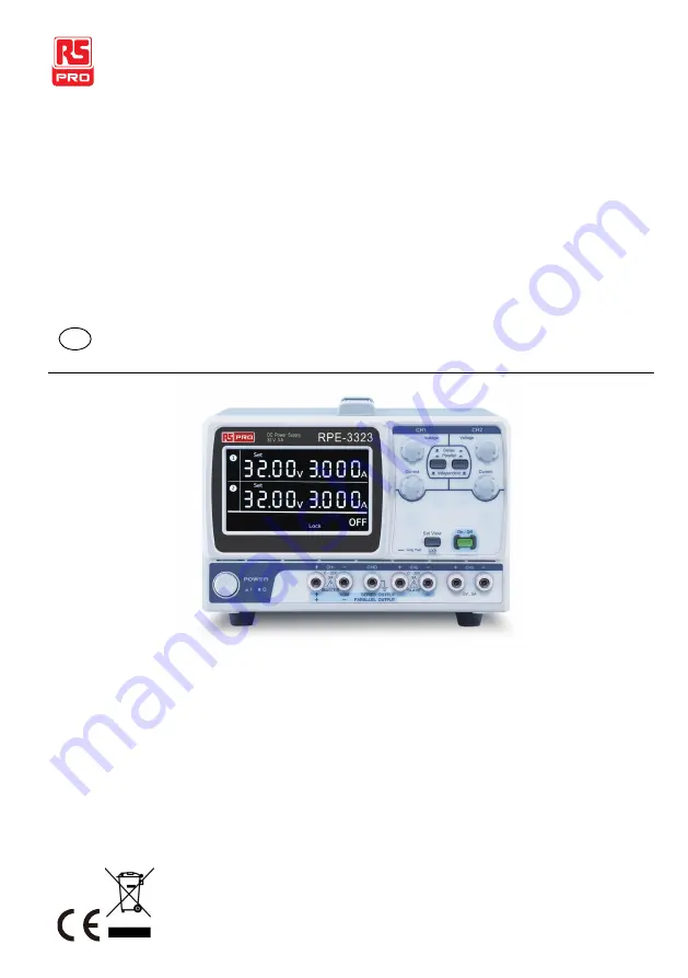
RPE-1326/2323/3323/4323
Multi-output DC Power Supply
EN
Page 1: ...Instruction Manual RPE 1326 2323 3323 4323 Multi output DC Power Supply EN ...
Page 2: ......
Page 3: ... SETUP 28 Power Up 28 Load Cable Connection 29 Output On Off 30 Select CH1 CH2 series or parallel mode 31 Switch between Channels 32 Setting Voltage Lock from Front Panel 33 Set the output state at startup 34 Set the displayed digit resolution for the voltage current 35 Remote Control Setting 36 OPERATION 37 CH1 CH2 Independent Mode 37 CH3 Independent Mode 40 CH4 Independent Mode 42 CH1 CH2 Series...
Page 4: ...RPE 1326 X323 Series Instruction Manual English 2 13 10 2016 Version No 001 FAQ 51 APPENDIX 52 Fuse Replacement 52 Specifications 54 Declaration of Conformity 57 INDEX 58 ...
Page 5: ...ration to insure your safety and to keep the best condition for the RPE 1326 2323 3323 4323 series Safety Symbols These safety symbols may appear in this manual or on the RPE 1326 2323 3323 4323 series WARNING Warning Identifies conditions or practices that could result in injury or loss of life CAUTION Caution Identifies conditions or practices that could result in damage to the RPE 1326 2323 332...
Page 6: ...the supplier from which this instrument was purchased Safety Guidelines General Guidelines CAUTION Do not place any heavy object on the device Avoid severe impacts or rough handling that leads to damaging the device Do not discharge static electricity to the device Do not block or obstruct the cooling fan vent opening Do not perform measurement at circuits directly connected to Mains see note belo...
Page 7: ...directly connected to the low voltage installation Measurement category I is for measurements performed on circuits not directly connected to Mains Power Supply WARNING AC Input voltage 100V 120V 220V 10 230VAC 10 6 50 60Hz Connect the protective grounding conductor of the AC power cord to an earth ground to avoid electrical shock Fuse WARNING Fuse type 100V 120V T6 3A 250V 220V 230V T3 15A 250V M...
Page 8: ...loth dampened in a solution of mild detergent and water Do not spray any liquid Do not use chemicals or cleaners containing harsh products such as benzene toluene xylene and acetone Operation Environment Location Indoor no direct sunlight dust free almost non conductive pollution note below Relative Humidity 80 Altitude 2000m Temperature 0 C to 40 C ...
Page 9: ...however a temporary conductivity caused by condensation must be expected Pollution degree 3 Conductive pollution occurs or dry non conductive pollution occurs which becomes conductive due to condensation which is expected In such conditions equipment is normally protected against exposure to direct sunlight precipitation and full wind pressure but neither temperature nor humidity is controlled Sto...
Page 10: ...is coloured Blue must be connected to the terminal which is marked with the letter N or coloured Blue or Black The wire which is coloured Brown must be connected to the terminal marked with the letter L or P or coloured Brown or Red If in doubt consult the instructions provided with the equipment or contact the supplier This cable appliance should be protected by a suitably rated and approved HBC ...
Page 11: ...are light weight adjustable multifunctional work stations The RPE 1326 has a single independent adjustable voltage output Coarse and fine The remote voltage compensation function is activated for large changes in current output The RPE 2323 has a 2 independent adjustable voltage outputs The RPE 3323 has three independent outputs two with adjustable voltage levels and one with fixed level 5V The RP...
Page 12: ...ltage is doubled in the parallel mode the output current is doubled The isolation degree from output terminal to chassis or from output terminal to output terminal is 500V Constant Voltage Constant Current Each output channel works in constant voltage CV or constant current CC mode Even at the maximum output current a fully rated continuously adjustable output voltage is provided For a big load th...
Page 13: ...r more details about CV CC mode operation see page 26 Automatic tracking mode The front panel display CH1 CH2 shows the output voltage or current When operating in the tracking mode the power supply will automatically connect to the auto tracking mode For more details about CH1 CH2 Series Tracking Mode see page 44 ...
Page 14: ...rent operation Series Tracking Parallel Tracking operation Output On Off control Multi output RPE 1326 32V 6A x1 RPE 2323 32V 3A x2 RPE 3323 32V 3A x2 5V 5A x 1 RPE 4323 32V 3A x2 5V 1A x1 15V 1A x1 Coarse and fine Voltage Current control RPE 1326 Output voltage compensation control RPE 1326 Function for locking the setting voltage CH1 CH2 Output voltage current setting view Set the displayed digi...
Page 15: ...OVERVIEW 13 10 2016 Version No 001 13 Protection Overload protection Reverse polarity protection Inadvertent voltage setting protection Interface Remote control Output ON OFF ...
Page 16: ... pre regulator and reference voltage source Main regulator circuit including the main rectifier and filter series regulator current comparator voltage comparator reference voltage amplifier remote device and relay control circuit The block diagram below shows the CH1 circuit arrangement The single phase input power is connected to the transformer through the input circuit Details of each part are ...
Page 17: ...voltage filtered by the capacitors C120 and C121 for the pre regulators U150 and U151 They provide a regulated voltage for other modules Main Rectifier The main rectifier is a full wave bridge rectifier It provides the power after the rectifier is filtered by the capacitor C101 and then regulated via a series wound regulator which is finally delivered to the output terminal Current Limiter U151 is...
Page 18: ...eries Instruction Manual English 16 13 10 2016 Version No 001 Overvoltage U131 is a comparator which activates when the unit is overloaded and it controls the output of U132 to turn off the output and inform the user ...
Page 19: ...lock CH3 Output CH2 Output CH1 Output CH4 Output GND Terminal CH1 CH4 Toggle Key Power Switch CH2 CH3 Toggle Key CH4 Voltage Knob CH1 Current Knob LCD The figure above is the front view of the RPE 4323 For views of other models please refer to physical device or see the panel overview for the other models on page 24 Display CH1 CH4 parameter display area parameter settings for the RPE 1326 ...
Page 20: ...area parameter readings for the RPE 1326 CH3 parameter display area for the RPE 3323 Status display area Output status display Voltmeter Displays output voltage of each channel RPE 4323 CH1 CH4 and CH2 CH3 RPE 2323 3323 CH1 and CH2 RPE 1326 Voltage setting readback 3 digits 4 digits CH3 display RPE 3323 ...
Page 21: ...CH1 or CH4 depending on which CH1 icon appears on the leaf hand side of the LCD display or CH4 is selected Each state is valid only when the output is ON When output is OFF the display is turns off CV CC OVP indicators for CH2 3 G P E 4 3 2 3 You can view the constant current constant voltage or OVP status for CH2 or CH3 depending on which CH2 icon appears on the leaf hand side of the LCD display ...
Page 22: ...thout pressing this function key When the output is on you can view the voltage current setting depending on which channel is selected The RPE 1326 displays both the reading and the setting values simultaneously without pressing this function key Channel indicator Indicates the currently selected channel The RPE 1326 doesn t have such display Output status of CH3 in the RPE 3323 When the output cu...
Page 23: ...nt features The fine tune range is about 1 10th of the present setting value CH1 3 and CH2 4 Views the channel settings or readback values for RPE 4323 voltage current Press the CH1 3 or CH2 4 key to toggle the view for the corresponding channels in the display Parallel Series Keys Activates parallel series tracking operation For details see page 44 The corresponding channel will be displayed on t...
Page 24: ... hold the key to lock and unlock the panel keys except OUTPUT For more information please refer to page 33 Output Key Turns the output on or off For more details see page 30 Power Switch G P E 1 3 2 6 Turns On or Off the main power For the power up sequence see page 28 Terminals GND Terminal G P E 4 3 2 3 Accepts a grounding wire CH1 Output G P E 4 3 2 3 Outputs CH1 voltage and current CH2 Output ...
Page 25: ...VIEW 13 10 2016 Version No 001 23 CH4 Output Outputs CH4 voltage and current The RPE 1326 Output terminal Output voltage and current The RPE 1326 Sense terminal G P E 1 3 2 6 1 3 2 6 Remote sense terminals ...
Page 26: ...1326 X323 Series Instruction Manual English 24 13 10 2016 Version No 001 Front views of the other three models RPE 1326 RPE 1326 RPE 2323 G P E 3 3 2 3 RPE 2323 G P E 1 3 2 6 RPE 3323 G P E 4 3 2 3 RPE 3323 ...
Page 27: ...n about the remote control terminal please see page 35 Power Cord Fuse Socket The power cord socket accepts the AC mains For power up details see page 28 The fuse holder contains the AC mains fuse For fuse replacement details see page 52 AC Selector Selects AC input voltage 100V 120V 220V 230V 50 60Hz ...
Page 28: ...appears on the LCD The Voltage level is kept at the setting and the Current level fluctuates according to the load condition until it reaches the output current setting CC mode When the current level reaches the output setting the RPE 1326 2323 3323 4323 series starts operating in Constant Current mode The CC indicator for the corresponding channel appears on the LCD The Current level is kept at t...
Page 29: ...OVERVIEW 13 10 2016 Version No 001 27 Diagram Vmax Imax Constant Voltage Constant Current Vout Iout ...
Page 30: ...lect AC voltage Before powering up the power supply select the AC input voltage from the rear panel Connect AC power cord Connect the AC power cord to the rear panel socket Power On Press the power switch to turn on the power The display will first display all the LCD segments before showing settings for each channel G P E 1 3 2 6 Power switch Press the power switch again to turn off the power G P...
Page 31: ...nal clockwise and tighten the screw Banana plug Insert the plug into the socket Wire type When using load cables other than the attached make sure they have enough current capacity for minimizing cable loss and load line impedance Voltage drop across a wire should not excess 0 5V The following list is the wire current rating at 450A cm 2 Wire size AWG Maximum current A 20 2 5 18 4 16 6 14 10 12 16...
Page 32: ...key again to turn off all outputs The OFF icon will become lit on the LCD display G P E 1 3 2 6 Automatic output off Any of the following actions during output on automatically turns it off Change the operation mode between independent series tracking parallel tracking When OVP is activated on a channel except CH3 on the RPE 3323 When the lock function is disabled When toggling to remote control ...
Page 33: ...urrent is twice than that of a single channel For details please see page 44 through to 49 Panel operation You can toggle the connection mode of CH1 CH2 by using different combinations of the mode selection key G P E 3 3 2 3 For the independent mode the right key is not pressed G P E 3 3 2 3 Toggle to parallel mode when both keys are pressed G P E 3 3 2 3 Right key is pressed and the left key is n...
Page 34: ...on the LCD display simultaneously To check and view the relevant information for the other channels you need to switch channels Please follow the steps listed below to switch between channels Panel operation Press the CH1 4 key to toggle between CH1 and CH4 The activated channel will be shown on the channel indicator G P E 4 3 2 3 Press the CH2 3 key to toggle between CH2 and CH3 The activated cha...
Page 35: ... reference levels The voltage lock function only applies to CH1 CH2 Panel operation Press the LOCK key for more than 2 seconds to lock the voltage knob operation for CH1 CH2 in the front panel The Lock icon will become lit G P E 4 3 2 3 To unlock press the LOCK key for more than 2 seconds The Lock icon will then turn off and the output turns off as well Note The OUTPUT key is not affected by the l...
Page 36: ...326 2323 3323 4323 series at its next startup There are two choices ON and OFF available for selection Panel operation 1 Press and hold the Output key and turn on the power until the On or OFF icon flashes on the LCD display G P E 1 3 2 6 2 Press the Set View key to select G P E 4 3 2 3 G P E 3 3 2 3 3 Press the ON OFF key to confirm G P E 1 3 2 6 Note By default the output is set to OFF at startu...
Page 37: ... readings to 3 or 4 digits at startup Panel operation 1 Press and hold the Set View key and turn the power until on the decimal point for the CH1 voltage flashes on the LCD display G P E 4 3 2 3 G P E 3 3 2 3 2 Press the Set View key to select the number of displayed digits G P E 4 3 2 3 G P E 3 3 2 3 3 Press the ON OFF key to confirm the selection G P E 1 3 2 6 Note By default the number of displ...
Page 38: ...ing This will put the power state ON OFF under remote control At this moment the On OFF icon flashes on the LCD display 2 Output control Pin 9 10 Open ON state Pin 9 10 Short OFF state Warring The remote control terminal can only be controlled by shorting external relay or jumper shunt opening the pins Voltage cannot be applied to the pins It is strictly prohibited to short pins 5 7 or 6 8 Pin 1 6...
Page 39: ...0 2016 Version No 001 37 OPERATION CH1 CH2 Independent Mode Background Connection CH1 and CH2 outputs work independent of each other CH1 LOAD CH2 LOAD RPE 4323 G P E 3 3 2 3 Output rating 0 32V 0 3A for each channel ...
Page 40: ...the Series Parallel key is not activated both the SER and PARA icons are off G P E 3 3 2 3 2 Connect the load to the front panel terminals CH1 CH2 G N D 3 Use the voltage and current knob to set the CH1 output voltage and current 4 Use the voltage and current knob to set the CH2 output voltage and current ...
Page 41: ...n No 001 39 5 Press the Output key to turn on the output The Output key will be lit and the ON icon will appear on the LCD display The CV or CC icon appears on the LCD to indicate the output status for each channel G P E 1 3 2 6 ...
Page 42: ...G P E 2 3 2 3 Output rating RPE 3323 5V 5A Max RPE 4323 0 5V 1A Max No Series Parallel Tracking CH3 doesn t have series parallel tracking mode Also the CH3 output is not affected by the CH1 and CH2 modes Panel operation 1 Connect the load to the front panel CH3 terminal 2 Select the output voltage For RPE 3323 5V RPE 4323 ...
Page 43: ...ey to turn on the output The Output key will be lit G P E 1 3 2 6 OVERLOAD RPE 3323 When the output current level exceeds 5 2A the overload icon appears on the LCD display and CH3 operation mode switches from constant voltage to constant current Overload CV CC RPE 4323 When the output current level exceeds the setting value the CV icon changes to the CC icon on the LCD display This indicates that ...
Page 44: ...ction The mode is used only for the RPE 4323 CH4 LOAD G P E 3 3 2 3 G P E 2 3 2 3 Output rating 0 15V 1A max No Series Parallel Tracking CH4 doesn t have series parallel tracking mode The CH4 output is not affected by the CH1 and CH2 modes Panel operation 1 Connect the load to the front panel CH4 terminal RPE 4323 ...
Page 45: ... on the LCD display to check the setting value G P E 4 3 2 3 3 Press the Output key to turn on the output The Output key will be lit G P E 1 3 2 6 CV CC When the output current level exceeds the setting value the CV icon changes to the CC icon on the LCD display This indicates that CH4 has switched from constant voltage to constant current CV CC ...
Page 46: ...4323 to combine the output by internally connecting CH1 Master and CH2 Slave in series CH1 Master controls the combined output voltage current level which is set independently The following describes two types of configurations depending on how common ground is used Series Tracking without Common Terminal Connection LOAD G P E 3 3 2 3 Output rating 0 64V 0 3A RPE 4323 ...
Page 47: ... to the front panel terminals CH1 CH2 Single supply G N D 3 Use the current knob to set the CH2 output current to the maximum level 4 Use the voltage and current knob to set the CH1 output voltage and current level 5 Press the Output key to turn on the output The Output key will be lit G P E 1 3 2 6 6 Refer to the CH1 Master meter and indicators for the output level and CV CC status ...
Page 48: ... meter Output current level CH1 meter reading shows the output current Series Tracking with Common Terminal Connection LOAD COM G P E 3 3 2 3 Output rating 0 32V 0 3A for CH1 COM 0 32V 0 3A for CH2 COM 1 Press the Series Parallel key to activate the series tracking mode The SER icon will be lit on the LCD display G P E 3 3 2 3 RPE 4323 ...
Page 49: ...ve output voltage the same level for both channels 4 Use the CH1 current knob to set the master output current 5 Use the CH2 current knob to set the slave output current 6 Press the Output key to turn on the output The Output key will be lit G P E 1 3 2 6 7 Refer to the CH1 Master meter and indicators for the output level and CV CC status CH1 Master voltage level CH1 meter reading shows the output...
Page 50: ...er current level CH1 meter reading shows the output current 8 Refer to the CH1 CH2 meter and CH2 indicators for the output level and CV CC status CH2 Slave voltage level The CH2 meter reading shows the output voltage CH2 Slave current level The CH2 meter reading shows the output current ...
Page 51: ...ne the output by internally connecting CH1 Master and CH2 Slave in parallel CH1 Master controls the combined output voltage current level LOAD G P E 3 3 2 3 Output rating 0 32V 0 6A 1 Press the Series Parallel key to activate the parallel tracking mode The PARA icon will be lit on the LCD display G P E 3 3 2 3 2 Connect the load to the CH1 terminals RPE 4323 ...
Page 52: ...is disabled 4 Press the Output key to turn on the output The Output key will be lit G P E 1 3 2 6 5 The operating mode of CH2 will appear as the CC icon on the LCD display 6 Refer to the CH1 meter and indicator for the output level and CV CC status Output voltage level The CH1 meter reading shows the output voltage Output current level Double the amount of CH1 current meter reading ...
Page 53: ... A2 No it simply means that the CH3 output current reached the maximum 5 2A and the operation mode turned from CV constant voltage to CC constant current You can continue using the power supply although reducing the output load is recommended Q3 The specifications do not match the real accuracies A3 Make sure that the power supply is powered on for at least 30 minutes within 20 C 30 C For more inf...
Page 54: ...6 X323 Series Instruction Manual English 52 13 10 2016 Version No 001 APPENDIX Fuse Replacement Steps 1 Take off the power cord and remove the fuse socket using a minus driver 2 Replace the fuse in the holder ...
Page 55: ...APPENDIX 13 10 2016 Version No 001 53 Rating 100V 120V T6 3A 250V 220V 230V T3 15A 250V ...
Page 56: ... CH1 CH2 Series 0 64V 0 3A CH1 CH2 Parallel 0 32V 0 6A CH3 5V 5A RPE 3323 0 5V 1A RPE 4323 CH4 0 15V 1A Voltage Regulation Line 0 01 3mV Load 0 01 3mV rating current 3A 0 02 5mV rating current 3A Ripple Noise 1mVrms 5Hz 1MHz Recovery Time 100µs 50 load change minimum load 0 5A Temperature Coefficient 300ppm C Current Regulation Line 0 2 3mA Load 0 2 3mA Ripple Noise 3mArms Tracking Operation Track...
Page 57: ...display Ammeter 3 200A full scale 4 digits or 3 digits 6 200A full scale 4 digits or 3digits RPE 1326 Voltmeter 33 00V full scale 4 digits or 3 digits Accuracy Setting Read back Accuracy Voltage 0 1 of reading 30mV 4digits 0 1 of reading 200mV 3digits Current 0 3 of reading 6mA 4digits 0 3 of reading 20mA 3digits RPE 1326 0 3 of reading 10mA 4digits RPE 1326 0 3 of reading 20mA 3digits CH3 on the ...
Page 58: ...ironment Ambient temperature 10 70 C Relative humidity 70 Power Source AC 100V 120V 220V 10 230V 10 6 50 60Hz Accessories User manual x1 Test lead Non European RPE 1326 GTL 104A x1 GTL 105A x1 RPE 2323 GTL 104A x2 RPE 3323 GTL 104A x3 RPE 4323 GTL 104A x2 GTL 105A x2 Test lead European RPE 1326 GTL 204A x 1 GTL 203A x 1 RPE 2323 GTL 204A x 2 RPE 3323 GTL 204A x 3 RPE 4323 GTL 204A x 2 GTL 203A x 2...
Page 59: ...6 1 EN 61326 2 1 Electrical equipment for measurement control and laboratory use EMC requirements 2013 Conducted Radiated Emission EN 55011 2009 A1 2010 Class B Electrical Fast Transients EN 61000 4 4 2012 Current Harmonics EN 61000 3 2 2014 Surge Immunity EN 61000 4 5 2006 Voltage Fluctuations EN 61000 3 3 2013 Conducted Susceptibility EN 61000 4 6 2014 Electrostatic Discharge EN 61000 4 2 2009 P...
Page 60: ... CC CH1 CH2 indicator 39 CH3 indicator 41 CH4 indicator 43 Operation theory 10 26 Declaration of conformity 57 Disposal instructions 7 EN61010 Measurement category 5 Pollution degree 7 Environment Operation 6 Specification 56 Storage 7 Front panel Lock manual 33 Overview 18 Fuse Rating 53 Replacement 52 Safety instruction 5 RPE series Block diagram 15 List of features 12 Operation theory 14 Techno...
Page 61: ... 30 Output voltage setting Manual 38 Over load indicator 41 Power supply Safety instruction 5 Setup 28 Socket overview 25 Specification 56 Protective ground symbol 4 remote output control terminal overview 25 Service operation About disassembly 4 Contact 51 tracking mode parallel 34 35 36 Tracking mode Operation theory 10 UK power cord 8 Warning symbol 3 Wire load 29 ...
Page 62: ...lect accident unauthorized repair alteration contamination or abnormal conditions of operation or handling Any implied warranties arising out of the sale of this product including but not limited to implied warranties of merchantability and fitness for a particular purpose are limited to the above RS Components shall not be liable for loss of use of the instrument or other incidental or consequent...
Page 63: ...ents Ltd Suite 23 A C East Sea Business Centre Phase 2 No 618 Yan an Eastern Road Shanghai 200001 China Europe RS Components Ltd PO Box 99 Corby Northants NN17 9RS United Kingdom Japan RS Components Ltd West Tower 12th Floor Yokohama Business Park 134 Godocho Hodogaya Yokohama Kanagawa 240 0005 Japan U S A Allied Electronics 7151 Jack Newell Blvd S Fort Worth Texas 76118 U S A South America RS Com...