RS PRO Iso-tech IPS 303A Manual Download Page 18

E15

5. MAINTENANCE


      The following instructions are for use by qualified personnel only. To avoid electrical shock, do not perform any

servicing other than contained in the operating instructions unless you are qualified to do so.

5-1  Fuse Replacement

If the fuse is blown, the CV or CC indicators will not light and the power supply will not operate. The fuse should not
normally blow unless a problem has developed in the unit. Try to determine and correct cause of the blown fuse, then
replace only with a fuse of the correct rating and type.
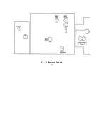
The fuse is located on the rear panel (see Fig. 3-2).

WARNING: For continued fire protection. Replace fuse only with 250V fuse of the specified type
and rating, and disconnect the power cord before replacing fuse.

5-2  Line Voltage Conversion

The primary winding of the power transformer is tapped to permit operation from 100, 120, 220, or 230 VAC, 50/60
Hz line voltage. Conversion from one line voltage to another is done by changing AC selects switch as shown in Fig. 3-
2.
The unit is set to default line voltage. To convert to different line voltage, perform the following procedure:

(1)


Make sure the power cord is unplugged.

(2)


Change the AC selects switch to the desired line voltage position.

(3)


A change in line voltage may also require a corresponding change of fuse value. Install the correct fuse value as
listed on rear panel.

5-3  Internal Adjustments

The unit was accurately adjusted at the factory before shipment. Readjustment is recommended only if repairs have
been made in a circuit affecting adjustment accuracy, or if you have a reason to believe the unit is out of accuracy.
However, adjustments should be attempted only if a multimeter with an accuracy of 

±

0.1% dcv or better is available.

WARNING

Summary of Contents for Iso-tech IPS 303A

Page 1: ...AUTION Caution statements identify conditions or practices that could result in damage to this product or other property The following symbols may appear in this manual or on the product DANGER High V...

Page 2: ...ent persons WARNING THIS APPLIANCE MUST BE EARTHED IMPORTANT The wires in this lead are coloured in accordance with the following code Green Yellow Earth Blue Neutral Brown Live Phase As the colours o...

Page 3: ...eter 3 2 5 Insulation 3 3 PANEL CONTROLS AND INDICATORS 4 3 1 Front Panel 4 3 2 Rear Panel 4 4 OPERATION INSTRUCTIONS 7 4 1 Precaution 7 4 2 Setting Current Limit 7 4 3 Constant Voltage Constant Curre...

Page 4: ...a coarse and fine potentiometer Both outputs can be accurately read on the voltmeter and ammeter Both stability and ripple are extremely good to meet the requirements of modern circuit design The unit...

Page 5: ...ature Humidity 10 C to 70 C 70 Maximum Altitude 2000m Installation Category II Pollution Degree 2 Product Designed for Indoor use only Accessories Fuse 1 Test lead GTL 105 current 4A 1 GTL 104 4A curr...

Page 6: ...Hz 1MHz rating current 3A Ripple Noise 1 0mVrms 5Hz 1MHz rating current 3A 5 Temperature coefficient 300ppm C 2 3 Constant Current Operation 1 Output current range 0 to rating current continuously adj...

Page 7: ...meter indicates the output current Analog type 12 A V selects switch selects whether he meter indicates the output voltage or current 13 Power control on off switch 14 Current HI LO control current in...

Page 8: ...E5 FIG 3 1 Front Panel...

Page 9: ...E6 FIG 3 2 Rear Panel...

Page 10: ...the current value on the Ammeter 5 The current limit overload protection has now been preset Do not change the CURRENT control setting after this step 6 Remove the short between the and terminals and...

Page 11: ...lt battery Initially the open circuit voltage of the power supply may be preset for 13 8 volts A low battery will place a heavy load on the supply and it will operate in the constant current mode whic...

Page 12: ...s when using identical models Two power supplies can be connected in series to provide a higher voltage and rating current output See Fig 4 2 for the connection scheme A Set power switch to OFF positi...

Page 13: ...E10 Fig 4 2 Connecting Two Power Supplies in Series...

Page 14: ...Set power switch to OFF position B Set the MASTER power supply INT SLAVE switch to INT position and set the SLAVE power supply INT SLAVE switch to PAR SLAVE position C Create a link from the MASTER p...

Page 15: ...E12 Fig 4 3 Connecting Two Power Supplies in Parallel...

Page 16: ...ltage source is connected to the SER input terminal and the line of control voltage source is connected to the power supply output terminal C The output voltage Eo is calculated as follows Eo Output v...

Page 17: ...The output current Io is calculated as follows Io Output current of the power supply Ir Rated current of the power supply Ec Remote control voltage 0 Ec approx 10V D For the remote control voltage sou...

Page 18: ...version The primary winding of the power transformer is tapped to permit operation from 100 120 220 or 230 VAC 50 60 Hz line voltage Conversion from one line voltage to another is done by changing AC...

Page 19: ...imeter to measure DC current at the output terminals of the power supply C Set the COARSE and FINE CURRENT controls to minimum fully counterclockwise D Adjust trimmer pot VR107 for a reading of 0 amps...

Page 20: ...E17 Fig 5 1 Adjustment Location...

Page 21: ...E18 Fig 5 2 Adjustment Location...

Reviews: