


E11
E.
When connected in series, the VOLTAGE controls of each power exercise control supply over 0 to rating range.
Add the two voltmeter readings together to determine the total output voltage, or an external voltmeter may be
connected across the load.
F.
Load current may be monitored from either supply; the readings will be identical since they are connected in
series. Also, since the supplies are connected in series, it is only necessary to set the current limit on one of the
supplies; the other may be set for maximum.
(3)
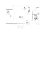
Parallel Operation
Two power supplies may be connected in parallel to provide rating voltage and higher current output. See Fig. 4-3 for
the connection scheme.
A.
Set power switch to "OFF" position.
B.
Set the “MASTER” power supply INT-SLAVE switch to “INT” position and set the “SLAVE” power supply
INT-SLAVE switch to “PAR-SLAVE” position.
C.
Create a link from the “MASTER” power supply “PAR” output terminal to the “SLAVE” power supply “PAR”
input.
D.
When connected in parallel ensure that the SLAVE VOLTAGE and CURRENT controls are set to maximum, then
adjust the MASTER controls to set the required VOLTAGE and CURRENT.
E.
The output voltage may be monitored from either supply; the readings will be identical since they are connected in
parallel, however the total output current can be determined by adding the two ammeter readings together, or an
external ammeter may be connected in series with the load.
F. Set the power switches to “ON” position.
G. Note: For correct operation ensure the MASTER output voltage is lower than 0.2-0.5V of the SLAVE output
voltage.