Instruction Manual
IIT 1601
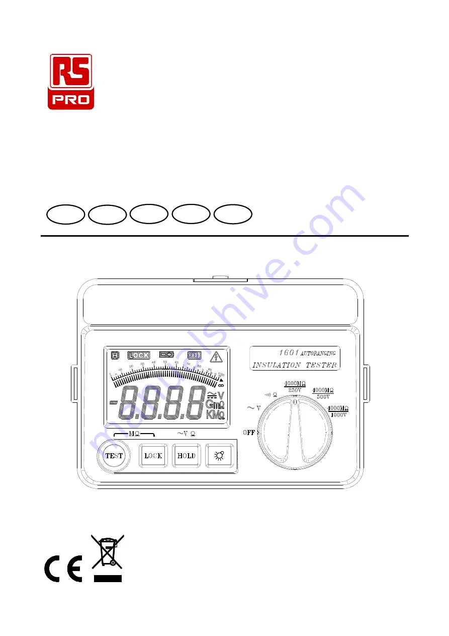
Autoranging Insulation Tester
FR
EN
IT
DE
ES
Page 1: ...Instruction Manual IIT 1601 Autoranging Insulation Tester FR EN IT DE ES...
Page 2: ...pecifications 4 2 PARTS CONTROLS 6 3 BEFORE OPERATION 7 3 1 How to connect test leads 7 3 2 Battery Check Replacement 7 3 3 Test Leads Check 7 4 AC VOLTAGE MEASUREMENTS 8 5 LOW RESISTANCE CONTINUITY M...
Page 3: ...ding crocodile clips must be in good order clean and have no broken or cracked insulation Do not push test button before all connection and preparation is done The instrument must only be used by suit...
Page 4: ...el Periodically wipe the case with a dry cloth Do not use abrasives or solvents on this instrument Display 80mm x 50mm LCD Display 3 3 4 Digital readout with analog bar indication Back light Operation...
Page 5: ...to 140 below 70 RH noncondensing Power Source DC12V 8 x 1 5V Size AA battery or equivalent Power Consumption Approx 90mA 4000M 1000V range Output open Circuit Approx 60mA 4000M 500V range Output open...
Page 6: ...Max open Circuit Voltage Max Short Circuit Current Overload Protection 400 0 1 1 5 12 8V 280mA 220Vrms Minimum Value 200mA Range Resolution Beeper Active Max open Circuit Voltage Overload Protection...
Page 7: ...erminal Voltage 4M 40M 400M 4000M 250V 250V 20 0 4M 40M 400M 4000M 500V 500V 20 0 4M 40M 400M 4000M 1000V 1K 3 5 2000M 5 5 2000M 1000V 10 0 Range Test Current Short circuit current 4000M 250V 250K loa...
Page 8: ...OLS LCD display Mega Ohm TEST button Maga Ohm TEST power LOCK button Data hold button Back light button Auto power OFF wake up Function selector Storage compartment Lo measuring terminal Hi measuring...
Page 9: ...b Use a screwdriver to unscrew the screw secured on battery cover Take out the used batteries and replace 8 x new batteries c Replace the battery cover and secure the screw 3 3 Test Leads Check Set t...
Page 10: ...he red test lead to the HI terminal and black test lead to the Lo terminal c Connect the tips of the test leads to both ends of the circuit under test and reading is displayed on the LCD d When the im...
Page 11: ...e deactivated and the test result will be held automatically b 3 Minutes Test Power Lock Mode Set the selector switch to the test voltage required Connect the test leads first to the instrument and th...
Page 12: ...be discharged automatically when the testing process is finished WARNING Do not proceed with this test unless the ACV reading of the circuit to be tested is Zero 7 AUTO POWER OFF The tester will turn...
Page 13: ...main power should be disconnected MOTORS AC Disconnect the motor from the line by disconnecting the wires at the motor terminals or by opening the main switch If the main switch is used and the motor...
Page 14: ...s and armature connect one megohmmeter lead to the grounded motor housing and the other lead to the brush on the commutator If the resistance measurement indicates a weakness raise the brushes off the...
Page 15: ...age from other equipment Check each conductor to ground and or lead sheath by connecting one megohmmeter lead to a ground and or lead sheath and the other megohmmeter lead to each of the conductors in...
Page 16: ......