


13/08/2017 Version No. 001
Oscilloscope Section/English
Oscilloscope Section/English
13/08/2017 Version No. 001
47
46
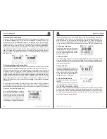
3 3 Serial Signal Measurement
To measure serial signals, as UART, IIC, SPI and etc, please take following steps:
1. Take 3.1 operations as reference, preliminary observe the measured signal.
2. Press “REC” while signal transmission.
3. Press “NEXT” or “Previous” according to prompt bar on the screen to check corresponding
page.
4. Take 3.2 (1) operations as reference, press “
”, “
” and “MODE” to move the cursor,
signal frequency can be measured.
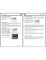
3-4 Analyze AC signal by FFT
Observe amplifying circuit in device, analyze output harmonic component and observe its
distortion by FFT.
To adopt FFT function, following steps can be taken.
1. Connect the input end of the amplifying circuit to sine wave signal.
2. Connect the oscilloscope probe to output end of amplifying circuit.
3. Take 3.1 operations as reference, proper signal can be observed.
4. Press ‘’F4 (FFT)”, observe frequency spectrum of output waveform for amplifying circuit
after Fast Fourier Transform.
5. Adjust the input signal source of amplifying circuit, observe FFT.
6. Press “F2 (
)” or “F3 (
)” to adjust position of red cursor, read corresponding
frequency and amplitude ratio of dominant wave and harmonic wave.
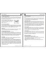
3-5 Waveform Save
Waveform data save should be operated under static state, three ways lead to “static” state.
1. Press “HOLD” + “F2 (SAVE)”;
2. Press “REC” + “F2(SAVE)’’;
3. Press “FFT” + “HOLD” + “F1 (SAVE)”;
Then operate according to screen prompts.
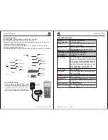
Fault Processing
4.1 General fault processing
(1) The Li-ion batter
1. If the screen goes black, please try one of the following:
y may be out of charge, please recharge it.
(2) Recharge the battery by matched charger for 5 to 10 minutes, try again.
(3) If still no display, Li-ion battery may be damaged, need to change.
2. Press “AUTO”, if waveform of signal doesn’t display on the screen, please take following
steps:
(1) Verify if the probe is correctly connected to signal cable.
(2) Verify if the signal cable is correctly connected to connector.
(3) Verify if the probe is correctly connected to measured object.
(4) Verify if the measured object emits signals.
-
4.
(5) Press “AUTO” to try again.
4.2 Waveform displays, but cannot stabilize.
(1) Check the trigger option is correct or not. Waveform stabilizes only proper trigger mode is
operated.
(2) Try to change “trigger mode” to falling edge or raising edge, waveform can not stabilize in
“no trigger” state.
(3) Try to change “
” button, weak signal is vulnerable to be interfered, and emits unstable
waveform.
4.3Waveform appears ladder shape:
Normal phenomenon. Level time-base gear may not be proper, adjust horizontal time-base
to raise the level resolution, display improved.