


13/08/2017 Version No. 001
MeterScope/English
MeterScope/English
13/08/2017 Version No. 001
25
24
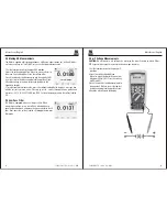
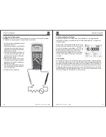
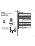
5-37.Replacing the Fuses
Referring to Figure , examine or replace the Meter's fuses as follows:
1.Turn the Meter off and remove the test leads from the terminals.
2.Remove the battery door assembly by using a standardblade screwdriver to turn the battery
door screw one-half turn counterclockwise.
3.Remove the fuse by gently prying one end loose, then sliding the fuse out of its bracket.
4.Install only specified replacement fuses.
5.Reinstall the battery door assembly and secure it by turning the screw one-half turn clockwise.
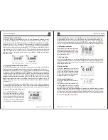
battery cover
Seal ring of
battery cover
7.4V Li-ion battery
Stand
Fuse wire
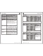
Stand
battery cover
7.4V Li-ion
battery
Seal ring of
battery cover
Back shell
Seal ring of
back Shell
Fuse wire
Fuse wire
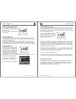
5-38.Li-ion Battery Charge
1.Set the function switch to the OFF/CHG position.
2.Insert the socket into the Meter Input port. And
the Adapter connected to the switch socket.
Then Insert the Adapter into Power socket.
3.Display charge symbol in TFT color LCD display.
Adapter
Socket
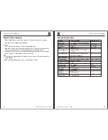
6.General Specification
Double molded, waterproof
6.5 feet (2 meters)
Test current of 0.9mA maximum, open circuit
voltage 3.2V DC typical
Audible signal will sound if the resistance is less
than 25
Ω
(approx.), test current <0.35mA
Captures peaks >1ms
Requires type K thermocouple
>10M
Ω
VDC & >9M
Ω
VAC
True RMS
The term stands for “Root-Mean-Square” which
represents the method of calculation of the voltage
or current value. Average responding multimeters
are calibrated to read correctly only on sine waves
and they will read inaccurately on non-sine wave
or distorted signals. True rms meters read
accurately on either type of signal.
50Hz to 100000Hz
<3 at full scale up to 500V, decreasing linearly
<
to 1.5 at 1000V
50,000 count backlit liquid crystal with bargraph
“OL” is displayed
5-30minutes (approximately) with disable feature
Automatic (no indication for positive); Minus (-)
sign for negative
20 times per second
“ ” is displayed if battery voltage drops below
operating voltage
Enclosure
Shock (Drop Test)
Diode Test
Continuity Check
PEAK
Temperature Sensor
Input Impedance
AC Response
AC True RMS
ACV Bandwidth
Crest Factor
Display
Overrange indication
Auto Power Off
Polarity
Measurement Rate
Low Battery Indication