background image

www.rovingnetworks.com


Version 1.01 9/28/2012


3


RN-XV-RD2-EVAL-UM

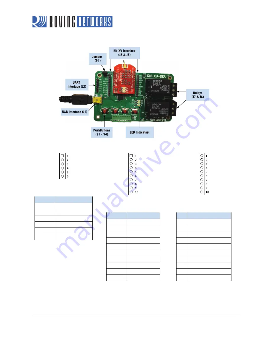
Figure 1. RN-XV-RD2 Evaluation Board 


UART Interface (J2) 


RX - input to evaluation board 

TX - output from evaluation board 


Pin 

Description 

VBUS (5 V) 

GND 

RXD 

TXD 

RTS

CTS 


RN-XV Interface (J3) 


RX - input to evaluation board 

TX - output from evaluation board 


Pin 

Description 

3.3 VDC output 

TXD 

RXD 

GPIO8 

RESET 

GPIO5 

GPIO7 

GPIO9 

GPIO1 

10 

GND 


RN-XV Interface (J5) 


RX - input to evaluation board 

TX - output from evaluation board 


Pin 

Description 

Sensor 2 (3.3-V tolerant) 

Sensor 3 (3.3-V tolerant) 

GPIO3 

Sensor 5 (3.3-V tolerant) 

CTS 

GPIO6 

Unused 

GPIO4 

RTS 

10 

GPIO14 


Summary of Contents for RN-171XVS-I/RM

Page 1: ...RN XV RD2 EVAL UM RN XV RD2 Evaluation Board USER MANUAL 2012 Roving Networks All rights reserved RN XV RD2 EVAL UM 1 01Version 1 0 9 28 2012 ...

Page 2: ...al temperature probe connector You can attach an external temperature probe to the board using the connector at SEN3 USB cable A USB cable connected to the board allows you to connect directly from the board to your computer e g for programming the module over the UART 10 GPIO pins The board contains access to 10 GPIO pins via the 3 3 V headers at J3 and J5 Voltage regulator The voltage regulator ...

Page 3: ...TXD 5 RTS 6 CTS RN XV Interface J3 RX input to evaluation board TX output from evaluation board Pin Description 1 3 3 VDC output 2 TXD 3 RXD 4 GPIO8 5 RESET 6 GPIO5 7 GPIO7 8 GPIO9 9 GPIO1 10 GND RN XV Interface J5 RX input to evaluation board TX output from evaluation board Pin Description 1 Sensor 2 3 3 V tolerant 2 Sensor 3 3 3 V tolerant 3 GPIO3 4 Sensor 5 3 3 V tolerant 5 CTS 6 GPIO6 7 Unused...

Page 4: ...rt on your computer Windows should automatically install the drivers for the cable If it does not download and install the FTDI drivers from the Support page on the Roving Networks website at http www rovingnetworks com support php Note the COM port to which you have attached the cable 3 Connect the USB cable to the evaluation board at J2 4 Attach a jumper to the pins at J1 if the board if it is m...

Page 5: ...mand mode and return to data mode type exit cr Basic configuration only requires the wireless network access point s name SSID and authentication password The WiFly module can only associate with one network at a time Roving Networks recommends that you begin your evaluation by configuring the WiFly module using an open access point to simplify the setup There are two ways to configure the WiFly m...

Page 6: ...9 For OS X if you are using CoolTerm you can view and select the port from within the application 2 Open your terminal emulation program 3 Specify the COM port If you are using TeraTerm select Serial and choose the COM port number from the Port drop down list box NOTE The default serial port setting for the WiFly module is 9600 baud 8 bits no parity and 1 stop bit Figure 3 Finding the COM Port Num...

Page 7: ...r example s uart baudrate 115200 is an illegal combination The WiFly module supports a variety of command keywords The Advanced User Manual which is available on the Support page of the Roving Networks website provides a complete command reference For evaluation purposes you may view the current settings using the get command get everything or get e in shorthand shows all parameters Table 3 shows ...

Page 8: ...with an access point type the following commands refer back to Figure 5 join roving1 or join 1 The space must be included between and 1 To disconnect from a network type leave cr The red LED blinks quickly when the WiFly module is not associated with an access point If you want the module to associate with a network automatically upon booting i e persistent configuration use the set wlan command w...

Page 9: ...e using hardware or software configuration NOTE the WiFly module only supports the OPEN mode for ad hoc networks Enable Ad Hoc Mode via Hardware To enable ad hoc mode using hardware set GPIO9 high 3 3 V at power up For the RN 134 board GPIO9 is on pin 1 on the jumper block J2 For the RN 174 board GPIO9 is on the J6 connector Upon power up with GPIO9 high the module creates an ad hoc network with t...

Page 10: ... RN XV IP address and netmask Because automatic IP assignment fixes the first two bytes of the IP as the netmask so that other devices connecting to the module can be reached You can set the netmask to a smaller subnet if the other device s IP addresses begin statically at the same subnet as HCP so that the module does not attempt to obtain an IP address from another device reboot The module will ...

Page 11: ...Once your computer is associated with the ad hoc network you can use the WiFly module s IP address to open a connection or connect using telnet as you would with an enterprise connection NOTE The WiFly module does not support ad hoc and infrastructure network modes simultaneously Once you have associated with the other network you can telnet into the WiFly module to configure it Open the telnet co...

Page 12: ...rks recommends purchasing the RN XV W which has a inch wire antenna Part Number Description RN XV RD2 Evaluation board RN 171XVW I RM Standard configuration industrial temperature Wi Fi 802 15 4 replacement solution with inch wire antenna For other configurations contact Roving Networks directly RN 171XVS I RM Custom configuration industrial temperature 40 o C to 85 o C Wi Fi 802 15 4 replacement ...

Page 13: ...www rovingnetworks com Version 1 01 9 28 2012 13 RN XV RD2 EVAL UM NOTES ...

Page 14: ...in the latest relevant information before placing orders and should verify that such information is current and complete Roving Networks assumes no liability for applications assistance or customer s product design Customers are responsible for their products and applications which use Roving Networks components To minimize customer product risks customers should provide adequate design and operat...

Reviews: