background image

READ & SAVE THESE INSTRUCTIONS 
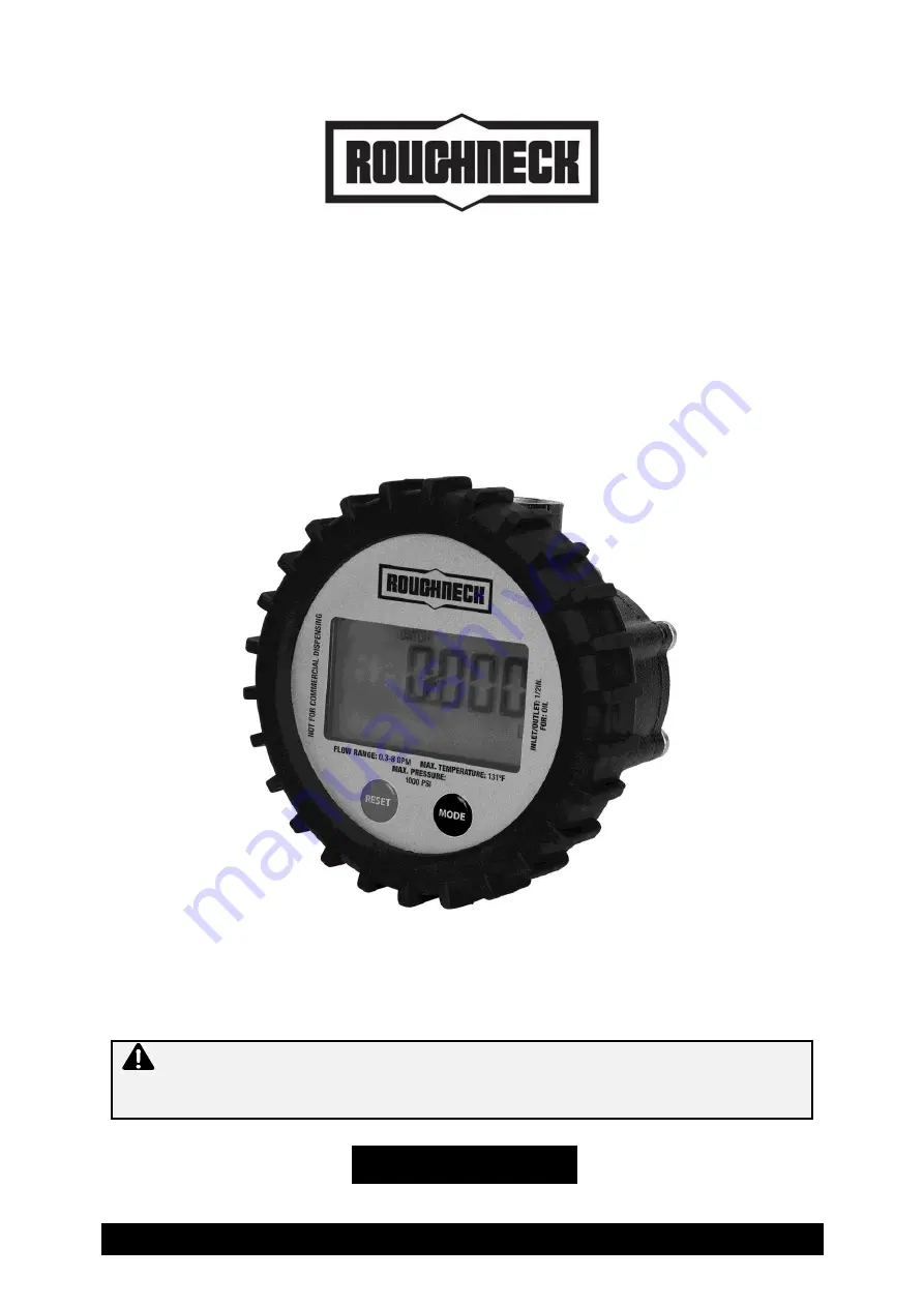


Digital Oil Meter 


Owner’s Manual 


WARNING:

 Read carefully and understand all ASSEMBLY AND OPERATION 

INSTRUCTIONS before operating. Failure to follow the safety rules and other basic safety 
precautions may result in serious personal injury. 


Item #67151 


Summary of Contents for 67151

Page 1: ...il Meter Owner s Manual WARNING Read carefully and understand all ASSEMBLY AND OPERATION INSTRUCTIONS before operating Failure to follow the safety rules and other basic safety precautions may result...

Page 2: ...at you read the entire manual to become familiar with this product before you begin using it This digital oil meter is designed for certain applications only Northern Tool and Equipment is not respons...

Page 3: ...ions 4 Important Safety Information 4 Specific Operation Warnings 6 Main Parts of Product 6 Installation Instructions 7 Before Each Use 7 Operating Instructions 10 After Each Use 10 Maintenance 10 Tro...

Page 4: ...9 units Max Non Resettable Totalizer 999999 units Least Count Resolution 0 0010 unit Filter Screen Included No Max Viscosity of Media SAE 140 1000 CP Option to Recalibrate by User Yes Protective Shro...

Page 5: ...resence of flammable liquids gases or dust The product can create sparks which may ignite the flammable liquids gases or dust Keep children and bystanders away from the work area while operating the t...

Page 6: ...storing the tool Such preventive safety measures reduce the risk of starting the tool accidentally Store the product when it is not in use Store it in a dry secure place out of the reach of children I...

Page 7: ...move the rubber shroud 1 Unscrew the four screws 2 with a Phillips head screwdriver in a diagonal sequence and separate the electronic module 3 from the meter body 5 2 Rotate the electronic module 3 i...

Page 8: ...f decimal places currently set on the main display 3 Press the MODE button to cycle through options available dEC 1 1 decimal place dEC 22 2 decimal places dEC 333 3 decimal places Configuring Units 1...

Page 9: ...Meter 1 The LCD will display CALIBRATE in the lower left hand corner as well as a number on the main display This represents the Test Volume to be dispensed through the meter during calibration 1 Pre...

Page 10: ...ng the RESET button for approximately 5 seconds Operating Instructions 1 Press the reset button before starting the operation 2 Pull the trigger to dispense oil and release it to stop dispensing While...

Page 11: ...al gears 6 4 Clean the meter body 5 with a soft brush or cloth Be careful not to damage the meter body or the gears 5 Assemble in the reverse order taking care of the following Position the oval gears...

Page 12: ...eaning the Meter Body Meter connections are over tightened Re adjust connections Fluid is too thick Use fluid of specified viscosity up to SAE 140 Insufficient accuracy Fluid flow rate is too high or...

Page 13: ...Page 13 of 16 Parts Diagram...

Page 14: ...Customer Service at 1 800 222 5381 Not all product components are available for replacement The illustrations provided are a convenient reference to the location and position of parts in the assembly...

Page 15: ...claim contact Us at 1 800 222 5381 identify the product by make and model number and follow the claim instructions that will be provided The product and the purchase receipt must be provided to Us in...

Page 16: ...Page 16 of 16 Distributed by Northern Tool Equipment Company Inc Burnsville Minnesota 55306 www northerntool com Made in India...

Reviews: