IN-E-HyFlex-V4_10
Rotronic AG
Bassersdorf, Switzerland
Document code
Unit
Instruction Manual
Document Type
HygroFlex transmitter version 4: instruction
manual
Document title
Page
31
of 61
© 2006; Rotronic AG IN-E-HyFlex-V2_10.doc
6.10 Grounding
Note that all input / output signal grounds - analog and digital - are tied together.
Ground the HygroFlex, especially if the electronics will be subjected to a low humidity environment
(35 %RH or less).
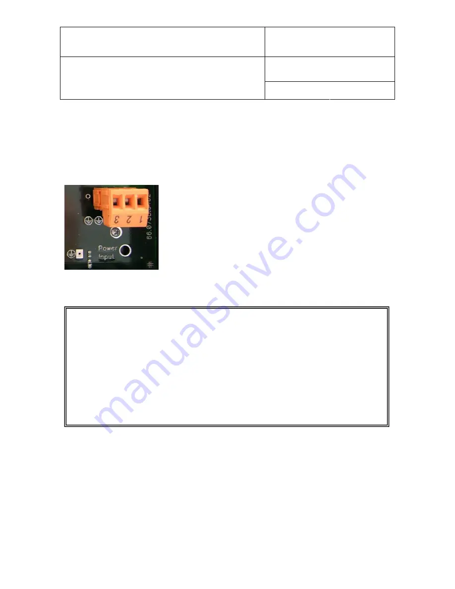
Starting with PCB version 66.0738.0402, there is no connection
between signal ground and terminal 3 of the power terminal block
(TB1). If so desired, a connection can be established by closing
solder pad B18, next to TB1. On previous versions of the PCB,
the signal ground and terminal 3 of TB1 were always tied
together.
6.11 RS-485 multi-drop network (HygroFlex 2 and 3)
Prior to connecting to the network
, configure each individual transmitter using the HW4
software (see separate instructions on the software CD ROM). With HW4 a Baud rate of either
19200 or 57600 may be used. As far as possible, use a Baud rate of 19200 for the HygroFlex
and
make sure that all devices in the multi-drop are set to the same Baud rate.
Proceed
as follows:
1) By default, all transmitters are shipped by the factory with RS address 0. If you plan
on using HW4 for your network, the RS address does not have to be changed as
HW4 will do this automatically once the RS-485 network has been established.
2) For easier identification, you may also want to give each transmitter a unique
descriptive name (maximum 30 characters).


