background image

IP Converter 

YT-930 

                                                                            Product Manual 


Ver. 1.23 

16 

Adjustments 

Before  our  product  is  dispatched  from  our  factory,  input  signal  against  supply  pressure  or  supply 

pressure against input signal will be set correctly. But, if additional setting requires, please see below. 

 
6.1 

Zero and Span Adjustments of Output pressure


(Based on 4~20mA / 0.02~0.1 MPa)


1) 

After wirings have been completed, please supply 4mA as input signal to YT-930. Please check 

output pressure and adjust zero adjustment bolt by using small (-) screw driver. In general, zero 

should be set at 0.02 MPa


2) 

Supply  20mA.  Please  check  output  pressure  and  adjust  span  adjustment  bolt  to  required  end 

output. In general, span should be set at 0.1 MPa.


3) 

Supply 4mA again. Please check the output pressure and repeat step 1 and 2 until required point 

have been set completely.   


4) 

Close the cover base completely


6.2 

Zero and Span Adjustments of Feedback Signal


  (Based on 4~20mA / 0.02~0.1 MPa)


1) 

Feedback signal requires DC 9~28V. Supply 4mA. Please check if the output pressure is at zero 

point and receive feedback signal correctly. If not, adjust zero adjustment bolt by using small (-) 

screw driver until the receiving feedback signal is set as 4mA.


2) 

Supply  20mA. Please check if the  output pressure  is at end point  and receive feedback signal 

correctly.  If  not,  adjust  span  adjustment  bolt  by  using  small  (-)  screw  driver  until  the  receiving 

feedback signal is set as 20mA 


3) 

Supply 4mA again. Please check the feedback signal and repeat step 1 and 2 until required point 

have been set completely.


4) 

Close the cover base completely before using the product.   


Summary of Contents for YT-930 Series

Page 1: ...IP Converter PRODUCT MANUAL YT 930 SERIES VERSION 1 23 Rotork YTC Limited ...

Page 2: ...ion Logic 9 2 8 Product Dimension 10 2 8 1 YT 930 series 10 2 8 2 YT 930 YT 200 AFR directly mounted Pressure gauge 11 3 Installation 12 3 1 Safety and Installation Tips 12 4 Connections Air 13 4 1 Safety 13 4 2 Supply Pressure Condition 13 4 3 Piping Condition 13 5 Connection Power 14 5 1 Safety 14 5 2 Terminal Overview 14 5 2 1 Input Signal Terminal 15 6 Adjustments 16 6 1 Zero and Span Adjustme...

Page 3: ...ation and operation 1 2 Manufacturer Warranty For the safety it is important to follow the instructions in the manual Manufacturer will not be responsible for any damages caused by user s negligence Any modifications or repairs to the product may only be performed if expressed in this manual Injuries and physical damages caused by customer s modifying or repairing the product without a prior consu...

Page 4: ...uld be used when explosion gases are present at the installation site Ring terminal with surface area of more than 1 25mm2 with M4 spring washer should be used to connect the power For external ground terminal ring terminal with surface area of more than 5 5mm2 should be used There is risk of explosion due to static electricity charge Static electricity charge may develop when cleaning the product...

Page 5: ... normally during sudden changes in supply pressure and or high vibration environment Air filter regulator YT 200 series can be directly installed without any pneumatic piping DA and RA can be set for the output pressure relative to the input current signal by simple switch operation DA and RA can be set for the feedback signal relative to the output pressure by simple switch operation Only feedbac...

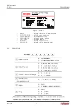
Page 6: ...onth and year 2 4 Product Code YT 930 1 2 3 4 5 6 1 Explosion Proof N i Non Explosion Intrinsic Safety ATEX IECEx 2 Output Pressure 1 2 3 4 0 02 0 1 MPa 0 2 1 bar 0 0 12 MPa 0 1 2 bar 0 04 0 2 MPa 0 4 2 bar 0 0 23 MPa 0 2 3 bar 3 Conduit Air Connection Type 1 2 G 1 2 Rc 1 4 G 1 2 1 4 NPT 4 Operating temp Non explosion proof 1 L 40 85 C 40 185 F 5 Option 0 1 None Feedback Signal 4 20mA DC 6 Gauge 0...

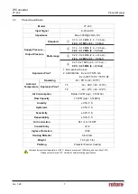
Page 7: ... ATEX IECEx Ex ia IIC T5 T6 Gb Ex ia IIIC T100 C T85 C Db Ambient Temperature Operating 40 85 C 40 185 F Explosion Proof T5 40 60 C 40 140 F T6 40 40 C 40 104 F Air Consumption Below 2 LPM sup 0 14 MPa Flow Capacity 70 LPM sup 0 14 MPa Linearity 0 5 F S Hysteresis 0 5 F S Sensitivity 0 2 F S Repeatability 0 3 F S Air Connection Rc 1 4 or 1 4 NPT Conduit Entry G 1 2 Ingress Protection IP 66 Housing...

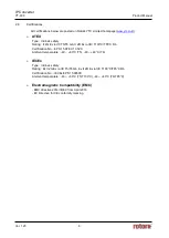
Page 8: ...D Ex ia IIIC T100 C T85 C Db Certification No EPS 15 ATEX 1 052 X Ambient temperature 40 60 C T5 40 40 C T6 IECEx Type Intrinsic safety Rating Ex II 2G Ex ia IIC T5 T6 Gb Ex II 2D Ex ia IIIC T100 C T85 C Db Certification No IECEx EPS 15 0059X Ambient temperature 40 60 C T5 T100 C 40 40 C T6 T85 C Electromagnetic Compatibility EMC EMC directive 2014 30 EC from April 2016 EC Directive for CE conform...

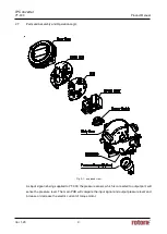
Page 9: ...ogic Fig 2 1 exploded view As input signal is being supplied to YT 930 the pressure sensor which is connected to output port will sense the pressure level The main PCB will compare the input signal and output pressure level and increase or decrease the electric current of torque motor ...

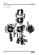
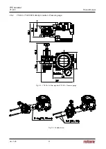
Page 10: ...IP Converter YT 930 Product Manual Ver 1 23 10 2 8 Product Dimension 2 8 1 YT 930 series Fig 2 2 YT 930 ...

Page 11: ...IP Converter YT 930 Product Manual Ver 1 23 11 2 8 2 YT 930 YT 200 AFR directly mounted Pressure gauge Fig 2 3 YT 930 Air filter regulator YT 200 Pressure gauge Fig 2 3 Exploded view ...

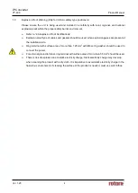
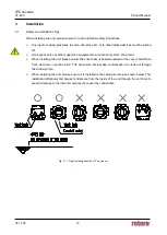
Page 12: ...system shut down When installing the unit please ensure the cover base is headed upward or the cover should face front as shown in section 2 8 2 This will ensure internal dew condensation can leak out through the draining hole When installing the unit please ensure it is installed in the same directions as shown below This installation effectively discharges condensate from the inside of the unit ...

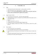
Page 13: ...r If require we recommend to use air filter regulator which contains 5 micron or lower filter YT 200 Avoid oil Comply with ISO 8573 1 or ISA 7 0 01 Is designed to be used with the pressure below 0 24 MPa 2 4 bar Set air filter regulator s pressure level 0 02 MPa 0 2 bar higher than required max output pressure 4 3 Piping Condition Ensure inside of pipe is clean of obstructions Do not use pipeline ...

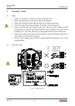
Page 14: ...ed cable with conductor section are 1 25mm2 and that is suitable for 600V complying with the conductor table of NEC Article 310 The outer diameter of the cable should be between 6 35 10mm Use shield wire to protect against electro magnetic field and noise Please do not install the cable near high noise equipment such as high capacity transformer or motor Please use shielded cable if necessary DO N...

Page 15: ...ocate cable entry of input signal on the left hand and bottom side of the product Insert cables into the conduit entry and secure them with and terminals on the plate Make sure to tighten bolts with 1 5 N m 15 kgf cm torque Please check the polarity of the terminals 4 There are one terminal inside and one outside for grounding 5 Ground resistance must be below 100 ohm 6 Close the cover base comple...

Page 16: ...MPa 3 Supply 4mA again Please check the output pressure and repeat step 1 and 2 until required point have been set completely 4 Close the cover base completely 6 2 Zero and Span Adjustments of Feedback Signal Based on 4 20mA 0 02 0 1 MPa 1 Feedback signal requires DC 9 28V Supply 4mA Please check if the output pressure is at zero point and receive feedback signal correctly If not adjust zero adjus...

Page 17: ...A and RA setting relative to the input signal The above figure shows a PCB with plastic PCB cover removed If the Output Pressure switch is switched to DA direction the output pressure increases when the current increases If it is switched to RA direction the output pressure decreases when the current increases ...

Page 18: ...o feedback signal Only feedback signal option If the Feedback Signal switch is switched to DA direction the feedback signal current increases when the output pressure increases If it s switched to RA direction the feedback signal current decrease when the output pressure increase ...

Page 19: ...C Limited Address 81 Hwanggeum ro 89 Beon gil Yangchon eup Gimpo si Gyeonggi do South Korea Postal code 10048 Tel 82 31 986 8545 Fax 82 70 4170 4927 Email ytc sales rotork com Homepage http www ytc co kr Issued 2021 02 22 Copyright Rotork YTC Limited All Rights Reserved ...

Reviews: