3.8
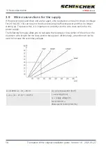
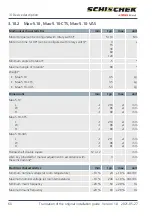
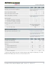
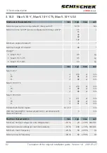
Power consumption as a function of supply voltage
Sizing of the on-site supply depends on the motor run time and supply voltage selected.
The values in the diagram are approximate, as there may be component variation within the
electronics.
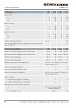
Nominal currents for size S
Nominal current as a function of motor run time
Motor run time
3 / 7.5
s
15
s
30
s
60
s
120
s
Voltage
24
V
DC
4.70
A
1.30
A
0.70
A
0.60
A
0.50
A
120
V
AC
0.75
A
0.30
A
0.25
A
0.20
A
0.17
A
240
V
AC
0.37
A
0.15
A
0.12
A
0.10
A
0.08
A
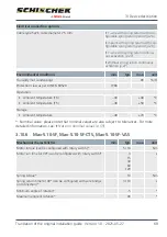
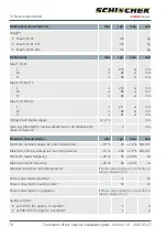
Nominal currents for size M
Nominal current as a function of motor run time
Motor run time
40
s
60
s
90
s
120
s
150
s
Voltage
24
V
DC
1.5
A
1.0
A
0.8
A
0.7
A
0.7
A
120
V
AC
0.26
A
0.18
A
0.14
A
0.12
A
0.12
A
240
V
AC
0.13
A
0.09
A
0.07
A
0.06
A
0.06
A
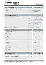
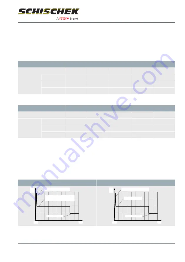
The holding power, irrespective of the run period, is typically 5 W. The heat output is ~ 16
W.
In heating mode, the motor is not running
.
When the supply voltage is switched on, the switching power supply for the drive needs ~
2.0 A to start up. The switch-on pulse lasts approx. 1 second. This must be taken into ac-
count when sizing the wire cross-section.
Depending on the motor run time, the power factor is between 0.8 and 0.5. There should
be a fuse on the power supply side with min. 2 AT.
Size S
Size M
Starting current pulse/output
Operating current/output
Caution: at 3 s motor run time the nominal
current is higher than the switch-on pulse!
Standby current/holding power
t [s]
I [A]/
P [W]
0
Starting current pulse/output
Operating current/output
Standby current/holding power
t [s]
I [A]/
P [W]
0
3 | Device description
Translation of the original installation guide · Version 1.0 · 2021-05-27
57

