- 7 -
www.rotork.com www.remotecontrol.se
Electrical wiring
1. Remove the ACTUATOR cover by loosening the four
captive cover bolts.
2. Confirm that the wiring diagram located in the
ACTUATOR and the wiring number on the nameplate
match with each other.
3. Confirm that the main power and supply described on
the nameplate of the ACTUATOR match with each other.
The two conduit entries on the SA-Series ACTUATOR
are PF1/2”. The ACTUATOR is sold worldwide, so there
maybe some differences as to the thread and pitch
standards. Check with your supplier to confirm which
standard is supplied in your area.
Wire Connection
Korea, Japan, China
PF 1/2”
Europe, UK, Australia, NZ
M20
US, Canada
NPT 1/2”
1. Standard conduit and conduit seal fittings may be used
when installing and wiring the ACTUATOR.
To prevent moisture and humidity from entering the
ACTUATOR, it is highly recommended that a seal fitting
be installed in the ACTUATOR conduit entry.
After all the conduit and wiring has been completed, then
the seal fitting can be sealed with packing and or a
potting material.
2. Any unused conduit entry must remain plugged with the
pipe plug provided with the ACTUATOR.
Do not remove the remaining plug as it is already sealed.
Main Power must only be applied when the top
cover is re-installed on the actuator body. If the
main power is on while wiring the actuator stop
work immediately and turn the power off. Only
then it is safe to proceed.
6. Be sure to wire and energize the heater as shown in
the wiring diagram.
7. Each ACTUATOR must be powered by their own
individual relays to prevent voltage feedback and
ACTUATOR damage.
8. After the wiring is completed in the ACTUATOR, use
wire ties to group the wires together and clean up
their appearance. Be certain that the wires are secure
and away from any moving parts.
Remove any loose debris before replacing the cover.
9. When all the work is completed, replace the top cover
and secure it using the four cover screws.
10. Apply power and do a final check to confirm proper
operation.
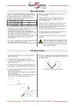
Interior/Exterior earth / ground terminal
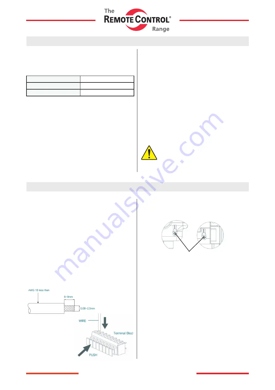
4. Connect the wire to the terminal strip according to the
wiring diagram provided.
The SA- Series ACTUATOR uses the push type WAGO
brand terminal strip.
The push type strip makes wiring connections easy and
also helps to protect against pipeline vibration.
5. Be sure to properly ground the ACTUATOR by using the
grounding lugs provided on the inside and outside of the
ACTUATOR body.


