5 Installation
Installer reference guide
7
RBRP069A61
ROTEX LAN adapter
4P510034-1 – 2017.10
5.3.3
To connect the indoor unit
INFORMATION
▪ In the indoor unit switch box, the cable is connected to
the same terminals the user interface is connected to.
For more information, see the installation manual of the
indoor unit.
▪ The 2 wires from the cable are NOT polarised. When
connecting them to the terminals, their polarity does
NOT matter.
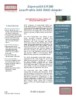
1
When entering the wiring from the bottom: inside the LAN
adapter casing, ensure strain relief by routing the cable along
the indicated cable path.
2
Connect indoor unit terminals X5M/1+2 to LAN adapter
terminals X3A/1+2.
X4A
X1A
X2A
X3A
X5M
2
1
5.3.4
To connect the router
X4A
X1A
X2A
X3A
NOTICE
To prevent communication problems due to cable
breakdown, do NOT exceed the minimum bend radius of
the Ethernet cable.
5.3.5
To connect the electrical meter
INFORMATION
This connection is ONLY supported by LAN adapter
RBRP069A61.
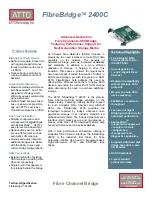
1
When entering the wiring from the bottom: inside the LAN
adapter casing, ensure strain relief by routing the cable along
the indicated cable path.
2
Connect the electrical meter to LAN adapter terminals X2A/1+2.
S1S
2
1
X4A
X1A
X2A
X3A
INFORMATION
Mind the polarity of the cable. The positive wire MUST be
connected to X2A/1; the negative wire to X2A/2.
INFORMATION
Make sure to connect the electrical meter in the correct
direction, so that it measures the total energy injected
INTO the grid.
5.3.6
To connect the digital inputs
INFORMATION
This connection is ONLY supported by LAN adapter
RBRP069A61.
INFORMATION
How the digital outputs are connected to X1A depends on
the Smart Grid application. The connection described in
the instructions below is for the system to run in the
"Recommended
ON"
operation
mode.
For
more
information, see
"7 Smart Grid application" on page 11
.
WARNING
Make sure X1A/N+L are protected by a fast acting circuit
breaker (rated current 100 mA~6 A).
WARNING
When connecting the wiring to LAN adapter terminal X1A,
make sure each wire is securely fastened to the
appropriate terminal. Use a screwdriver to open the wire
clamps. Make sure the bare copper wire is fully inserted
into the terminal (bare copper wire CANNOT be visible).
1
3
2
1
Ensure strain relief by fastening the cable with a cable tie to the
cable tie mounting.
2
Provide a detection voltage to X1A/N+L. Make sure X1A/N+L
are protected by a fast acting circuit breaker.
3
For the system to run in the "Recommended ON" operation
mode (Smart Grid application), connect the digital input to the
X1A/1+2 LAN adapter digital input.
Summary of Contents for RBRP069A61
Page 15: ......