15
6) LIFT FIXING
After making electric and hydraulic connections, make sure they are properly connected. Now fix the lift to the floor, using the bases as
templates, drill a hole into the floor a 18 mm.Ø bit must be used up to a depth of about 150 mm., clean the holes, place the proper
inserts with light hammer blows and finally tighten the bolts. In case of an inground, lift, check it is perfectly centred. (To open the lift see
chapter “4” INSTALLATION).
7) FIRST STARTING
Warning! Only skilled and authorized personnel should be allowed to perform these operations.
Carefully follow all instructions shown below to prevent possible damage to the car lift or risk of injury to people.
Be sure that the operating area is cleared of people.
After positioning the lift as specified, and performing electric and hydraulic connections the lift can be operated by the procedures shown
below: Open the door of the control box and unscrew the oil tank cap, and using a funnel pour about 10 l. of ESSO NUTO H 32
hydraulic oil or equivalent. Move the master switch to “1” position (see pag. 4) and simultaneously press “lifting” and “limit switch cut out”
push buttons (see pag.4 pos. 1-4) keep them pressed until P1 comes to a stop. If motors rotate but lifting operations cannot be
performed, check motor for proper direction of rotation, exchange the phases if necessary. Add. 5 l. of oil in the tank and press again the
two buttons until P2 platform stops. To lower the car lift, press the “lowering” button. Repeat lifting/lowering operations three or four
times. In case the platforms do not start simu
ltaneously, it is necessary to set the adjustable TIMER “S2” (see dwg. on page 12) as
follows: Place the selectors, following the drawing on page 12 in order to increase or decrease the opening time of the levelling valve.
The opening time of the (EL) valve allows the hydraulic circuit, between piston p1 and piston p2, to go through the levelling valve (EL)
and load the necessary pressure which guarantees the simultaneous start of the platforms. If the pressure is not sufficient in the
hydraulic circuit, t
he platform p1 will start first. If the pressure is too high, the platform p2 will start first. (“Start” refers to the initial surge)
This operation is to be done with no load on the lift for 4/5 times and afterwards repeated with a load between 1500/2000 kg. this last
operation is necessary only as a check.
CHAPTER 5
– OPERATION
OPERATION SEQUENCE
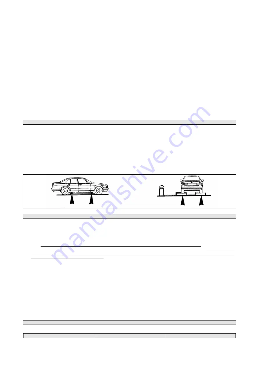
Be sure the platforms are at their minimum height before driving on/off the lift. Get in the vehicle and drive on the lift; be sure the vehicle
is centred and both rear and front wheels are properly positioned, place the proper rubber pads on the platform so that they are in line
with the lifting points specified by the manufacturer. Press the “lifting” button,keep it pressed until the required height is reached. To
lower the lift press the “lowering” button. During the lowering, the lift will stop automatically for some seconds at approximately 30 cm.
from the floor, producing a safety acoustic signal, so the lift lowers again.
During the first hours of operation cracking noises could occur. This is due to the natural settlement of mechanical parts and
will disappear during the following hours of operation.
CHECKS
Perform the following checks when operating the car lift.
•
Carefully check the car lift and its load during lifting/lowering operation.
•
Check the warning acoustic signal of the car lift during lowering operation.
CHAPTER 6
– MAINTENANCE
WARNING!
Only skilled and authorized personnel should be allowed to service the lift. When servicing the lift, all safety precautions
must be followed to avoid accidental starting of the machine. The master switch must be padlocked in “zero” position. During service
operations, “safety” precautions must always be followed.
PERIODIC MAINTENANCE
Maintenance operations must be performed at each specified maintenance period in order to keep the car lift in perfect working
condition. The manufacturer is not liable for possible damage resulting from failure to follow the above instructions.
•
Car lift must be cleaned once a month, as least, without using chemical agents and hight pressure washing guns. Always dispose of
used brake oil to prevent possible damage to the finishing. Carefully check that piston rods are not damage since inside seals could
be seriously damaged and leakage of oil occur.
•
Check safety devices for proper working condition periodically.
•
Grease roller slideways periodically.
•
Check flexible tubes for proper conditions yearly.
•
Change hydraulic system oil at 5 year intervals, at least.
Used oil is a highly pollutant product. Always dispose of used oil as
specified by the effective law of the country where the car lift is installed.
MACHINE DEMOLITION
When demolishing the machine all safety precautions specified in chapter
“3”-”4” must be followed. Only authorized technicians should
be allowed to perform this operation. Metallic parts can be scrapped as “scrap iron”. In any case, demolished material must be
eliminated according to the effective laws of the country where the car lift is installed. It must remembered that, for fiscal purposes, any
demolition operation must be properly documented as specified by the effective laws of the country where the lift is installed at the time
of demolition.
CHAPTER 7 - SYMPTOMS AND SOLUTIONS
– TROUBLESHOOTING
Troubleshooting and possible repairs require absolute compliance with all safety precautions indicated in chapter “6 -
maintenance” and chapter “3 - safety”.
SYMPTOM
POSSIBLE CAUSE
PROBABLE SOLUTION
Summary of Contents for GLP99SM
Page 1: ...SCISSOR LIFT FREE WHEELS GEMINI LOW PROFILE OPERATING INSTRUCTIONS GLP99SM GLP99SM P...
Page 9: ...9 WIRING DIAGRAMS...
Page 10: ...10 WIRING DIAGRAM...
Page 11: ...11 WIRING DIAGRAM...
Page 18: ...18...
Page 19: ...19 FIG 3 LEVERS AND PISTON FIG 4 PLATFORM...
Page 20: ...20 FIG 5 CONTROL BOX...
Page 21: ...21 FIG 6 ELECTRIC COMPONENTS FIG 7 SAFETY ELEMENTS FIG 8 RAMPS...


