SA-59
GSM Communicator
Installation and User Manual
Page 1: ...SA 59 GSM Communicator Installation and User Manual ...
Page 2: ...al property rights covering the subject matter in this manual TEXTS IMAGES AND ILLUSTRATIONS INCLUDING THEIR ARRANGEMENT IN THIS DOCUMENT ARE SUBJECT TO THE PROTECTION OF COPYRIGHT LAWS AND OTHER LEGAL RIGHTS WORLDWIDE THEIR USE REPRODUCTION AND TRANSMITTAL TO THIRD PARTIES WITHOUT EXPRESS WRITTEN PERMISSION MAY RESULT IN LEGAL PROCEEDINGS The furnishing of this manual to any party does not give t...
Page 3: ... 7 2 Technical Specifications 8 3 Installation 9 3 1 General 9 3 1 1 LED Indicators 9 3 1 2 I O Description 9 3 2 Wiring 10 3 3 Mounting 11 4 Messaging Types 12 4 1 SMS Messaging Types 12 5 Programming 13 5 1 Programming the System 13 5 1 1 Prefix Number Programming 13 5 1 2 Phone Number Programming 14 A Limited Warranty 15 ...
Page 4: ...List of Figures iv SA 59 Installation and User Manual List of Figures Figure 1 SA 59 Components 9 Figure 2 Wiring Diagram 10 ...
Page 5: ...List of Tables SA 59 Installation and User Manual v List of Tables Table 1 LED Indicators 9 Table 2 I O Description 9 Table 3 Inputs 11 ...
Page 6: ...erefore not all functions described in this manual may be available in the specific system and or product configuration you purchased Incorrect operation or installation or failure of the user to effectively maintain the system relieves the manufacturer and seller from all or any responsibility for consequent noncompliance damage or injury The text images and graphics contained in the manual are f...
Page 7: ...the system to which it is connected When the SA 59 is connected to a telephone line Line IN the SA 59 directs the device to a land line to make a call If the land line is cut or not functioning all communications go via the GSM network without the need for any special additional settings If the SA 59 is not connected to a land line all communications take place via the GSM network The SA 59 incorp...
Page 8: ...ollector outputs of 200 mA Relay 1 Form C 1A relay related to Input 1 Telephone Lines Telephone line out and telephone line in LEDs 5 LED indications Connections PSTN Telephone Line IN Connected to the main telephone line in the premises before any other connection Telephone Line OUT Should be connected to the alarm system Environmental Characteristics Operating Temp Range 0 C to 60 C 32 F to 140 ...
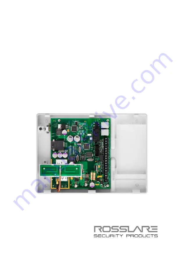
Page 9: ... ON Power supply is connected to device D3 Transmission Transmission of signal to antenna D4 Reset Reset in power up D1 GSM Power up ready Power up the device LD21 Dialing telephone device 3 1 2 I O Description Table 2 describes the I O activation Table 2 I O Description Input Activation Input activation triggers the outputs in the following order Input 1 Activate Output 1 Input 2 Activate Output ...
Page 10: ...s so that when the input is set to 0 grounded the output is activated When the input is set to 1 not connected the output returns to its steady state 3 2 Wiring Figure 2 shows the main components on the SA 59 board including terminal blocks and LED indicators Figure 2 Wiring Diagram ...
Page 11: ...input 2 Input 3 Logical input 3 Input 4 Logical input 4 Line OUT Telephone Line OUT from system to telephone device Line IN Telephone Line IN from the entrance point to the system To wire the SA 59 1 Connect Line IN to the phone line and Line OUT to the alarm sytem 2 It is suggested to connect the tamper to the Input 1 and Output 1 to the alarm system to receive an indication of tampering with the...
Page 12: ...by changing the 4th input in the SA 59 4 1 SMS Messaging Types Input Sent Message Input 1 high SYSTEM TROUBLE Input 1 low SYSTEM TROUBLE RESTORE Input 2 high PANIC ALARM Input 2 low PANIC RESTORE Input 3 high SYSTEM ARMED Input 3 low SYSTEM DISARMED Input 4 high SYSTEM ALARM When system indicates SYSTEM TROUBLE the input has switched from 0 V connected to ground to a non connected state tri state ...
Page 13: ... is not connected to PSTN lines The default installer code is 5555 5 1 1 Prefix Number Programming When using the GSM network the addition of a prefix number may be needed The prefix number is user programmable To program the prefix number 1 Press 5555 to enter Program mode 2 Press 1 3 Type the prefix number 4 Press to confirm The unit beeps Example For prefix number 9 press 5555 1 9 To delete the...
Page 14: ...mber 4 Press to confirm The unit beeps Example For number 052646666 press 5555 2 052646666 To program additional phone numbers 1 Press 5555 to enter Program mode 2 Press 3 For the third phone number Press 4 instead of 3 3 Type the prefix number 4 Press to confirm The unit beeps Example For the number 052525222 press 5555 3 052525222 To delete phone numbers 1 Press 5555 to enter Program mode 2 Pres...
Page 15: ...mited Warranty The full ROSSLARE Limited Warranty Statement is available in the Quick Links section on the ROSSLARE website at www rosslaresecurity com Rosslare considers any use of this product as agreement to the Warranty Terms even if you do not review them ...
Page 16: ...osslaresecurity com Europe Rosslare Israel Ltd Rosh HaAyin Israel Tel 972 3 938 6838 Fax 972 3 938 6830 support eu rosslaresecurity com Latin America Rosslare Latin America Buenos Aires Argentina Tel 54 11 4001 3104 support la rosslaresecurity com China Rosslare Electronics Shenzhen Ltd Shenzhen China Tel 86 755 8610 6842 Fax 86 755 8610 6101 support cn rosslaresecurity com India Rosslare Electron...