ACO-2200 User Guide (v5.0)
DashBoard Menus • 29
Slot 1 - Channel Setup Tabs
Select the
Slot 1 - Channel Setup
node to configure the personality of the ACO-2200 and to set up individual
channels for the required input signal type to be measured.
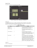
Figure 7.2 Example of the Slot 1 - Channel Setup Tabs
Status Tab
The Status tab reports the following information:
• the number of channels installed on the ACO-2200
• the current changeover mode
• whether the primary or backup SRG-2200 is on air
Auto Recover Settings
This area displays the following read-only fields:
•
Recover Mode
— indicates how the ACO-2200 is configured for recovery from faults.
•
Recovery Delay in Seconds
— indicates how many seconds the optional recovery delay is set for.
•
Recovery Delay in HHMMSS
— indicates how much time optional recovery delay is set for.
•
Recovery Delay Countdown
— when a fault occurs and is then fixed, if the ACO-2200 is set to auto recovery
after delay, this timer shows the time until the ACO-2200 switches back to the Primary SRG-2200.
Primary Error Channel Status
Each field can display:
• a green indicator (OK) when there are no errors to report on the specified channel; or a
• red indicator for fault for each primary and backup channel.
Configuration Tab
Use the options in this tab to configure the ACO-2200.


