


Rosen Aviation
Remote Display System
Document Number: 105478
Revision: F
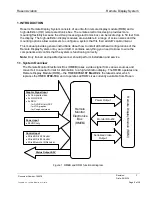
Date: 06/23/14
Template: 4.4.1.6FM2; Revision A; 12/06/12
Page 9 of 38
Attach the 32” cosmetic back to the bulkhead using six
#6 100
FHP screws
(customer supplied).
Attach the 42” cosmetic back to the bulkhead using ten
#6 100
FHP screws
(customer supplied).
Attach the 55”
cosmetic back to the bulkhead using twelve #6 100
FHP screws
(customer supplied).
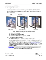
Figure 4 3201-, 4201-, and 5501-800 cosmetic back mounting bracket
4.2. Attaching an RDM to a Cosmetic Back
Figure 5 shows an exploded view of a proud-mount assembly. Align the tabs on the RDM with the
mounting brackets on the cosmetic back. Secure with two 4-40 fasteners in each tab/bracket. The
number of mounting brackets varies by RDM size. For more dimensional information, see the
technical drawings for your specific assembly.
Figure 5 RDM with a proud-mount bezel assembly
Attach to
bulkhead
Attach to
RDM
Mounting brackets
on the cosmetic
back


