background image

The information in this user guide is subject to change without notice. 
 

Copyright © 2007 Rose Point Navigation Systems.  
All rights reserved. 


Rose Point Navigation Systems is a trademark of Rose Point Navigation Systems. The names of any other 
companies and/or products mentioned herein may be the trademarks of their respective owners. 


WARNINGS: 

Use the Radar at your own risk.  

REVIEW: Need something about how you don’t want to get hit by the spinning thing and that it is 
emitting microwave energy so you should not look at it or be near it. 

The Radar is intended to be used as a supplementary aid to navigation and must not be considered a 
replacement for other prudent navigation techniques. The captain of a vessel is ultimately responsible 
for its safe navigation and the prudent mariner does not rely on any single source of information. 


Rose Point Navigation Systems 

16150 NE 85th Street 
Suite 210 
Redmond, WA 98052 
 
Phone: 425-605-0985   
Fax: 425-605-1285 
e-mail: [email protected] 
 
www.rosepointnav.com 


Summary of Contents for MDS-51

Page 1: ...ROSE POINT RADAR INSTALLATION GUIDE Your guide to installing the Rose Point Radar PRELIMINARY 11 9 2007 ...

Page 2: ...ow you don t want to get hit by the spinning thing and that it is emitting microwave energy so you should not look at it or be near it The Radar is intended to be used as a supplementary aid to navigation and must not be considered a replacement for other prudent navigation techniques The captain of a vessel is ultimately responsible for its safe navigation and the prudent mariner does not rely on...

Page 3: ...Control Box to your Navigation Computer 17 Installing the Radar Software 18 Calibrating the Radar 19 Installation Angle 19 Parking Angle 19 Transmission Trigger Delay 19 STC Curve Preset 19 Manual Gain Preset 19 Manual STC Preset 19 Auto Gain Preset 19 Auto STC Preset 19 Auto Harbor STC Preset 19 Troubleshooting 20 Warranty 21 Return Policy 22 Specifications 23 Radar Sensor Unit 23 Power 23 Interf...

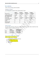
Page 4: ...MDS 5 1 MDS 5 1 MDS 6 1 MDS 6 Power Supply Cable 1 2m 1 2m 1 2m 1 2m Tapping Screw 4 4 4 4 Fuses 6 6 6 6 Ethernet Cable 1 1 1 1 Power Switch 1 1 1 1 Optional Cables If you will need a cable longer than 10m the following lengths are available Please contact Rose Point Navigation Systems for ordering information MDS 51 MDS 52 61 62 15m 242J158055B 242J159098B 20m 242J158055C 242J159098C 30m 242J1580...

Page 5: ...the power supply system including wiring by using a circuit tester Power Supply Requirements The radar sensor power supply may provide anywhere from 10 2 to 41 6 VDC The following table describes the current requirements at 12 and 24 VDC 12 VDC 24 VDC MDS 51 5A 2 5A MDS 52 6A 3A MDS 61 7A 3 5A MDS 62 8A 4A Fuse Requirements For the radar sensor to be operated safely fuses with the proper rating mu...

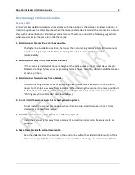
Page 6: ...reating shadow zones or generating false echoes Therefore do not install the scanner at such a position 3 Install scanner forward away from obstacle To avoid creating shadow zones or generating false echoes install the scanner at a position nearer to the ship s bow away from obstacles When installing the scanner on a mast position it in front of the mast If obstacles cannot be avoided for the ship...

Page 7: ...n be obtained by calculation depending on the distance from the scanner to obstacles using the following equation Shifting from keel line Obtaining sufficient dip angle Raise the scanner position so that there is a sufficient dip angle available between the line of sight from the scanner to the obstacle and the horizontal line By raising the dip angle above 5 degrees it is possible to prevent mid ...

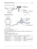
Page 8: ...te When the radar mast or mounting bracket has a curvature of more than 2mm repair it or use spacers Mounting Base Referring to Hole positions for mounting scanner open holes in diameter of 12 mm 0 47 in at five locations in the mount base and use these holes to fix the scanner unit to the mount base with hexagonal bolts Use the template included with this manual The bolts included with your radar...

Page 9: ...n Guide 6 Mounting the radome scanner Mounting the open array scanner Use a silicon sealer to prevent the bolts from becoming loose The Radome may be damaged if you use locking putty Bolts for mounting Scanner Unit Radome scanner ...

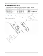
Page 10: ... Scanner Installing the Open Array Antenna Remove the protective cap covering the rotary coupler on the top of the scanner Match the antenna radiation direction to the direction of the arrow markings on the rotation base and secure the antenna in position using four M8 bolts ...

Page 11: ...ay Choose the proper bolt length according to the thickness of the surface on which you are going to install the control box Hole diameter is different when using bolts rather than tapping screws When using tapping screws drill appropriately sized holes When using bolts and nuts drill holes in diameter of 6 mm 0 24 in Hole positions for the control box ...

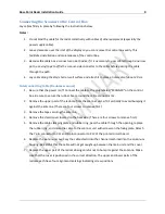
Page 12: ...box Be sure to secure the rubber boot around the cable connector rim 2 Remove the upper part of the radome from the scanner unit Lift it vertically to avoid bumping it against the antenna There are four screws to remove first 3 Remove the tape securing the antenna 4 Remove the shield cover located on the backside There are four screws to remove first 5 Remove the cable clamping plate and rubber ri...

Page 13: ...Rose Point Radar Installation Guide 10 Attaching the Cover Radome scanner ...

Page 14: ...Rose Point Radar Installation Guide 11 Attaching the interconnecting cable Radome Scanner ...

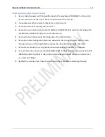
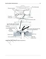
Page 15: ...718A Pull out the transceiver 5 Remove the four bolts securing the fixing plate at the cable entrance 6 Remove the metal fixing plate rubber seal and washer that secure the cable Pass the cable through as shown in the diagram below replace the above items and tighten the bolts 7 Return the transceiver to its original position and secure it with the bolts you removed 8 Connect the 7 pin connector t...

Page 16: ...Rose Point Radar Installation Guide 13 Attaching the interconnecting cable Open Array Scanner ...

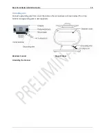
Page 17: ...tallation Guide 14 Grounding wire Connect a grounding wire from one of the bolts on the scanner base as shown below The crimp terminal and grounding wire is user supplied Randome Scanner Open Scanner Grounding the Scanner ...

Page 18: ...included with your radar to the receptacle labeled POWER on the control box and connect to power supply as followings The red and green wires are not used and should be covered with electrical tape to prevent a short circuit Place the fuse and connection part in a dry area where water will not splash When extending the power supply cable use a suitable cable as below ...

Page 19: ...n and blue wires together and cover with electrical tape The On Off control switch does not carry the main power for operating the RADARpc scanner unit 1 Route the green and blue wires to the location for the On Off control switch 2 If you choose to use the switch provided refer to the diagram below to layout and cut a rectangular hole for the switch 3 Pass the green and blue wires through the hol...

Page 20: ...r a network can be made with an Ethernet hub switch or router Cross over cables adapters hubs switches and routers can all be found at most computer supply stores We recommend that you use a standard home router or gateway to create a small local area network on your boat and connect your radar and your navigation computer to that network TODO Mention some specific routers that we have tested TODO...

Page 21: ...Rose Point Radar Installation Guide 18 Installing the Radar Software TODO Write about how to enable the radar features in Coastal Explorer ...

Page 22: ...ating the Radar TODO Write about how to setup all of the calibration settings Installation Angle Parking Angle Transmission Trigger Delay STC Curve Preset Manual Gain Preset Manual STC Preset Auto Gain Preset Auto STC Preset Auto Harbor STC Preset ...

Page 23: ...Rose Point Radar Installation Guide 20 Troubleshooting TODO Write a troubleshooting section Be sure to include Network connection issues Errors reported by the radar unit ...

Page 24: ...scretion SUCH REMEDY SHALL BE YOUR SOLE AND EXCLUSIVE REMEDY FOR ANY BREACH OF WARRANTY THE WARRANTIES AND REMEDIES CONTAINED HEREIN ARE EXCLUSIVE AND IN LIEU OF ALL OTHER WARRANTIES WHETHER EXPRESS IMPLIED OR STATUTORY INCLUDING ANY LIABILITY ARISING UNDER ANY WARRANTY OF MERCHANTABILITY OR FITNESS FOR A PARTICULAR PURPOSE STATUTORY OR OTHERWISE IN NO EVENT SHALL ROSE POINT NAVIGATION SYSTEMS BE ...

Page 25: ...us to obtain a refund you will be issued an RMA number that must accompany the return NO EXCEPTIONS Proof of purchase in the form of a dated invoice receipt or packing slip is required for refunds NO EXCEPTIONS Customers will be responsible for freight shipping when returning a unit for refund Products with physical damage or signs of abuse tampering may not be credited for a full refund When retu...

Page 26: ...Rose Point Radar Installation Guide 23 Specifications Radar Sensor Unit Power Interface ...

Page 27: ...Rose Point Radar Installation Guide 24 Drawings Interconnection Diagram ...

Page 28: ...Rose Point Radar Installation Guide 25 RB715A Scanner Unit ...

Page 29: ...Rose Point Radar Installation Guide 26 RB716A Scanner Unit ...

Page 30: ...Rose Point Radar Installation Guide 27 RB717A 718A Scanner Unit ...

Page 31: ...Rose Point Radar Installation Guide 28 MDS 5 MDS 6 Control Box ...

Reviews: