background image

INSTALLATION 

UltraVista LC Installation and Operations Manual 


UltraVista LC Installation 

Installation of the UltraVista LC is an easy process.  The installation consists 
of installing the LCD displays, mounting the UltraVista LC unit, connecting 
all of the cables, adjusting the output resolution settings, and adjusting the 
bezel to align the images. 

Installing the LCD Displays 

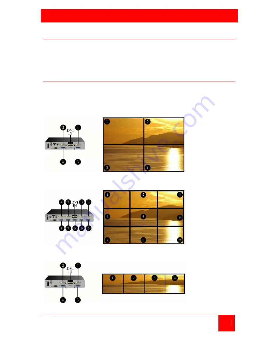
Mount the LCD monitors as shown in figure 1, 2, 3 and 4.  All displays 
should be identical in size and resolution capabilities.  When mounting the 
displays, keep the horizontal and vertical gaps between displays consistent.  
(See attachment C for optional panel mounting configurations) 


Figure 1. 2 x 2 Installation 


Figure 2. 3 x 3 Installation 


Figure 3. 1 x 4 Installation 

Summary of Contents for UltraVista LC

Page 1: ...UltraVista LC Video controller splitter 10707 Stancliff Road Phone 281 933 7673 Houston Texas 77099 WWW ROSE COM INSTALLATION AND OPERATIONS MANUAL ...

Page 2: ...CHANTABILITY AND FITNESS FOR A PARTICULAR PURPOSE ARE LIMITED IN DURATION TO A PERIOD OF ONE YEAR FROM THE DATE OF PURCHASE AND NO WARRANTIES WHETHER EXPRESS OR IMPLIED WILL APPLY AFTER THIS PERIOD SOME STATES DO NOT ALLOW LIMITATIONS ON HOW LONG AN IMPLIED WARRANTY LASTS SO THE ABOVE LIMITATION MAY NOT APPLY TO YOU IF THIS PRODUCT IS NOT IN GOOD WORKING ORDER AS WARRANTED ABOVE YOUR SOLE REMEDY S...

Page 3: ...um CR VI Polybrominated Biphenyls PBB Polybrominated Diphenyl Ethers PBDE Housing X O O O O X Display X O O O O X Printer Circuit Boards X O O O O X Metal Fasteners X O O O O O Cable Assembly X O O O O X Fan Assembly X O O O O X Power Supply Assemblies X O O O O X Battery O O O O O O O This toxic or hazardous substance is contained in all of the homogeneous materials for the part is below the limi...

Page 4: ...on 7 Installing the LCD Displays 7 Bezel compensation value calculation 8 Mounting the UltraVista LC unit 9 Connecting the cable 9 Using the built in OSD features 10 OSD Menu Structure 11 Mask Control 12 Link Control 12 Slave Mask Setting 13 Settings 14 Warning 14 Information 15 Slave Output Resolution 15 Sync and Power 15 Firmware Information 16 Serial Number 16 Remote controller 16 Safety 18 Ser...

Page 5: ...dels can be expanded to produce a 4x4 or a 9x9 video array Connect the UltraVista LC directly to a laptop or desktop computer with a single DVI cable and instantly the hi definition computer image is displayed on a large video wall No extra set up is required because the UltraVista LC automatically detects the correct settings The UltraVista LC can be automatically configured to produce three outp...

Page 6: ...Easy adjustments for bezel compensation Expand a 2x2 model easily to a 4x4 display a 3x3 model to a 6x6 or a 9x9 display array Configure the 1x4 model with 4 monitors arranged horizontally Adjustments and control can be performed using a remote control or serial commands from a connected computer Compatible with most monitor that supports DVI input Displays can be LCD HD Plasma DLP Projectors or o...

Page 7: ... UltraVista LC and other products offered by Rose Electronics that are designed for data center applications classroom environments and many other access and switching applications Product Registration Take advantage of the following when you register your Rose Electronics products online at http www rose com htm online registrationform htm Rose Standard Warranty Plus Free Lifetime Firmware Update...

Page 8: ...MODELS 4 UltraVista LC Installation and Operations Manual UltraVista LC 1x4 model UltraVista LC 2x2 model UltraVista LC 3x3 model ...

Page 9: ...ideo In Indicator LED indicates a valid input video signal is present Power Indicator LED indicates that power is applied to the unit Menu select button Displays the OSD Selects items and sets new item values Up arrow button Moves the selection up Down arrow button Moves the selection down Left arrow button Moves the selection left Right arrow button Moves the selection right Enter button Selects ...

Page 10: ...nc In Sync Out Connects from and to additional units Serial DB9F connector Connects to an external computer s serial port for external configuration and control TOP DVI D video out connector BOTTOM DVI I video out connector NOTE DVI I connector supports both digital and analog signals DVI D video in connector ...

Page 11: ...sting the output resolution settings and adjusting the bezel to align the images Installing the LCD Displays Mount the LCD monitors as shown in figure 1 2 3 and 4 All displays should be identical in size and resolution capabilities When mounting the displays keep the horizontal and vertical gaps between displays consistent See attachment C for optional panel mounting configurations Figure 1 2 x 2 ...

Page 12: ...entered into the OSD to set the gap compensation which will produce a smooth transition from one display to the next Figure 4 Bezel calculation Calculate the values of X and Y to enter into the OSD as shown below See the OSD section for instructions Bezel Width mm Viewable Width mm X value X Viewable Width mm 4 Bezel Height mm Viewable Height mm Y value X Viewable Height mm 4 Bezel Viewable Width ...

Page 13: ...distances are needed from the UltraVista LC to the video source or to the display monitors Rose Electronics video extender line can extend this distance up to 400 feet using CATx cabling or 6 miles over fiber cabling Connecting the cable Attach the provided DVI video cable from the UltraVista LC DVI input connector to the DVI video source If the video source is VGA a VGA to DVI converter must be u...

Page 14: ...rce to the unit Connect each display monitor to the unit Connect a serial cable from the unit to a controlling computer Using the built in OSD features To invoke the built in OSD press the MENU button on the front panel The OSD will display on the monitor connected to the DVI output port 1 Note All cable connections and power must be applied Serial cable ...

Page 15: ...nits DVI Displays DVI output settings with link on Displays individual settings with link off X Sets the horizontal mask value Slave Mask Setting 2x2 and 3x3 only Y Sets the vertical mask value OUT Sets the output resolution Settings MODE Sets the output mode Warning Change Setting Warning that the output resolution OUT Displays the Units output resolution Information IN Displays the Units input r...

Page 16: ...nu window Example Pressing the Menu button displays the Mask Control window With no item selected pressing the right arrow button will display the Link Control window press the right arrow button again and the Slave Mask Setting window will display Following are examples and descriptions of each menu item Mask Control The mask control menu compensates for the gaps between the monitors Selection De...

Page 17: ...Mask Setting Mask Link ON All slave units have the same settings Mask Link OFF DVI 1 settings for unit 1 DVI 2 settings for unit 2 DVI 3 settings for unit 3 DVI 4 settings for unit 4 X displays the horizontal bezel setting Y displays the vertical bezel setting ...

Page 18: ... UltraVista LC 2x2 unit S 2x1 mode on the UltraVista LC 2x2 unit C 1x1 mode on the UltraVista LC 2x2 unit 3x3 3x3 mode on the UltraVista LC 3x3 unit 2x3 2x3 mode on the UltraVista LC 3x3 unit 3x2 3x2 mode on the UltraVista LC 3x3 unit Warning The warning message indicates that the output resolution on the computer should be adjusted to the resolution value shown ...

Page 19: ...urrent input and output resolutions Slave Output Resolution Shows the current slave output resolution DS x slave setting for designated unit 1 H horizontal resolution for the designated unit V vertical resolution for the designated unit Sync and Power SYNC for debugging Power Turns unit power OFF ...

Page 20: ... serial number Remote controller All UltraVista LC models are supplied with a remote control The remote control provides the same functions as the front panel push buttons Power Turns the UltraVista LC unit on or off Menu Displays the OSD menu on monitor 1 selects items and sets new values Left Moves the selection left Right Moves the selection right Up Moves the selection up Down Moves the select...

Page 21: ...onitor Check that the monitor is turned on Check that the power source for the monitor is turned on Check that the power source has the correct power rating Make sure the LCD panel power cables are securely fastened to the monitor and to the power source Check the monitor is connection ...

Page 22: ...ection cables clear of obstructions that might cause damage to them Use only power cords power adapter and connection cables designed for this Unit Keep objects that might damage this Unit and liquids that may spill clear from this Unit Liquids and foreign objects might come in contact with voltage points that could create a risk of fire or electrical shock Do not use liquid or aerosol cleaners to...

Page 23: ...ainer or equivalent insured and shipped to Rose Electronics Attn RA__________ 10707 Stancliff Road Houston Texas 77099 USA Technical Support If you are experiencing problems or need assistance in setting up configuring or operating your QuadraVista consult the appropriate sections of this manual If however you require additional information or assistance please contact the Rose Electronics Technic...

Page 24: ...DVI W D H Dimensions 2x2 model 9 0 x 7 1 x 1 85 Inches 230 x 180 x 47 mm 3x3 model 11 6 x 7 4 x 1 85 Inches 295 x 188 x 47 mm Power Adapter Input 90 VAC to 264 VAC 47 Hz to 63 Hz Power Adapter Output 11 52 V to 12 48 V 2 1 A 25 W Power Consumption 2x2 model 10 W 3x3 model 17 W Safety and Emission CCC CE FCC Temperature 0ºC 40ºC ...

Page 25: ... 103 0014 東京都中央区日本橋蛎殻町 1 16 11 TEL 03 3668 8089 FAX 03 3668 9872 URL http www cybernetech co jp ...

Reviews: