


8
CrystalView DVI Mini Installation and Operations Manual
Single-Head model
1. DVImm cable from Transmitter to computer
2. USB Type A/B cable from Transmitter to computer
3. DVI monitor to Receiver
4. USB keyboard to Receiver
5. USB mouse to Receiver
6. CATx cable from Transmitter to Receiver
Dual-Head model has two of each cable, monitor, keyboard, mouse, and
CATx cable.
Dip Switch Settings
The configuration Dip-Switches are located on the front panel of
the transmitter and the receiver units.
The Dip-Switches on the transmitter are used to set the monitor
resolution. The default switch setting (Automatic control - #1 and #2 Off)
will automatically adapt to the remote monitor resolution. The default
setting should only be modified if the cable length goes to or beyond
the specified limits or the image quality is not satisfactory.
Switch #4 selects the operating mode; standard or firmware update.
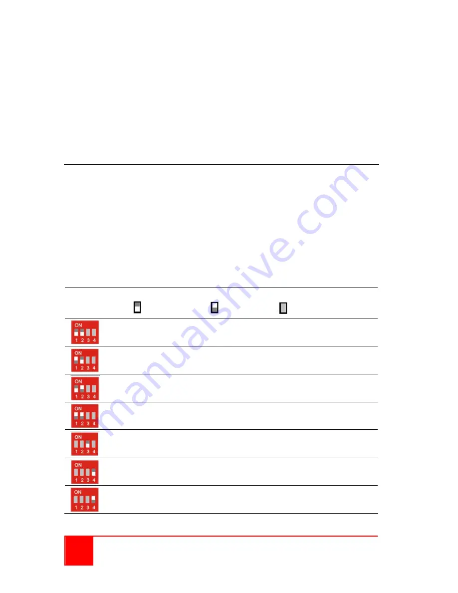
Transmitter Dip-switch settings
DIP Switch
Position
Function
= Switch down
= Switch up
= Switch not used
Monitor Resolution: Automatic control (Default)
Monitor Resolution: up to 1280 x 1024
Monitor Resolution: larger than 1280 x 1024
Configuration for Maximum Distance transmission,
Independent of Monitor Resolution
Reserved – currently w/o function
Operation mode: Standard operation (Default)
Operation mode: Firmware update
Set only during Firmware Update, if required
Figure 5. Transmitter Dip-switch settings