7
Rosco Maximizer 2B Asphalt Distributor
7-7
Maintenance
Relief Valve
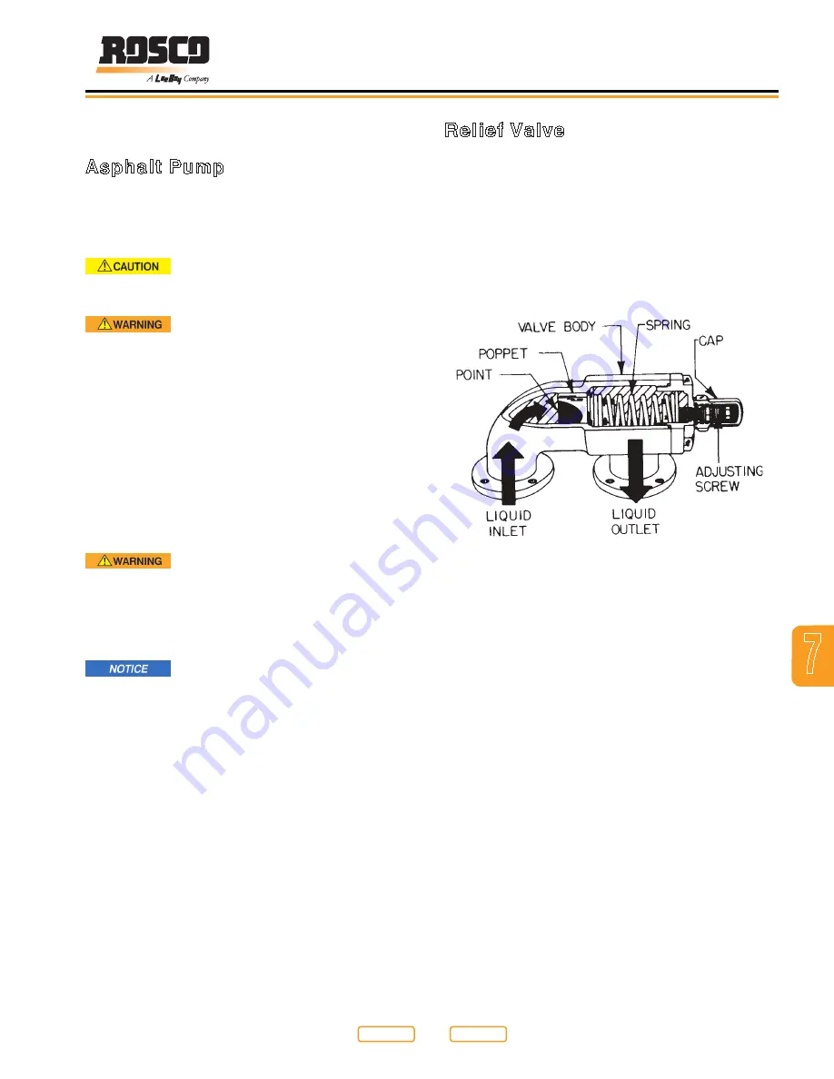
The asphalt circuit is designed with a relief valve (
) to prevent damaging components when the system
pressure gets too high . To adjust the relief pressure,
follow this procedure:
1 . The valve is set at the factory to 70 PSI for all
operating conditions .
2 . To check the relief pressure, there must be material
in the tank . Stop the engine, place all controls in
neutral, set park brake and remove ignition key .
Relief Valve
Figure 7-3
3 . Be sure the machine is cool to the touch .
4 . Restart the engine . Turn the Plus One Controller
Master switch ON .
5 . Set the Plus One Controller Mode Selection button
to RVS SUCT (Reverse Suction) . Set the Auto/
Manual setting to MANUAL and run the pump IN
REVERSE at 200 GPM (757 Lpm) .
6 . Slowly open the 3/4 inch (19 .05 mm) plug on top of
the strainer box and listen for a suction sound . If
sound is heard, remove the plug and install a 0-100
PSI pressure gauge with diaphragm (Rosco part
#5058) to the screen box . (
sound is not heard, check all switches to be sure
the right settings are being used .
7 . After the gauge is installed, set the Plus One
Controller Mode button to SPRAY/BAR CRCLT for 3
to 5 minutes . Then set the Spraybar Master switch
to OFF . Manually run the pump FORWARD at 300
GPM (1135 .6 Lpm) . Check the pressure . It should
read 70 PSI . If it does not, adjust with the adjusting
screw .
Asphalt Pump System
Asphalt Pump
The asphalt pump input shaft uses a special material
that is packed into a cavity around the shaft to seal the
hot material in the pump . To adjust this seal, follow this
procedure:
Always wear protective clothing,
gloves and a face shield Contact with hot asphalt
can cause severe burns
DO NOT SMOKE around the machine
Fuel, asphalt material and the fumes from either
can explode when exposed to flame or heat from
smoking or other sources
1 . Stop the engine, place all controls in neutral, set the
park brake and remove ignition key . Be sure that all
components are cool to the touch before adjusting .
2 . Visually inspect the pump on a weekly basis for
shaft leakage . Correct adjustment of the packing
gland will allow for a slight weeping at the shaft . If
there is no weeping, the gland is probably too tight
and shaft damage could occur . If more than slight
weeping is observed, tighten the packing gland .
Fire Hazard! Never spray cleaning
solvent or release agent near a heating element or
near any open flame or source of ignition. Do not
operate Burner System during cleaning! Cleaning
solvent and release agent could ignite causing
serious personal injury
When using washdown, consider the
environment and do not allow cleaning solvent to run
onto the ground
NOTE: When in CLEAN-OUT Mode, a small amount of
cleaning solvent or release agent may leak from
the shaft . This is normal .
3 . To adjust the packing material, tighten the bolts on
the packing gland . Tighten both bolts one half (1/2)
turn and check for seepage . Readjust if required .
Adjust the mounting bolts an equal amount each
time to maintain an even pressure on the packing
material .
4 . Replace packing material when gland adjustment
does not stop shaft leakage .
Return to
Last Viewed
Return to
Thumb Index
Summary of Contents for Maximizer 2B
Page 2: ......


