Rorke Data Galaxy RAIDGHDX2-2130-16iSCSI Installation And Hardware Reference Manual Download Page 87

Galaxy GHDX2-2130-16iSCSI Installation and Hardware Reference Manual  


D-SUB 9 and Audio Jack Pinouts


C-2 

6 DSR 

(Shorted) 

7 RTS 

(Shorted) 

8 CTS 

(Shorted) 

9 NC 

Table C-1: COM1 Adapter Cable CN1 and 

CN2  Pin Out Definitions 


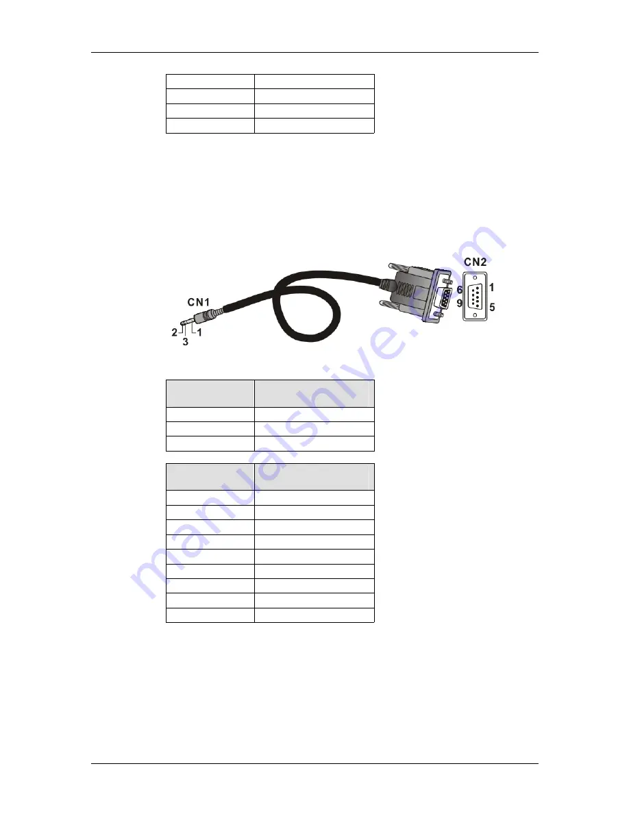
C.1.2  COM2 Serial Port Cable to UPS 

COM2 Cable:

 Use this cable to connect the COM2 port to a UPS. 

PN: GAL-9270CUPSCab 


Figure C-2: Connector Pinouts - Adapter Cable for COM2 


CN1 Pin Number  Pin Name 

1 Ground 


2 TXD 

3 RXD 


CN2 Pin Number  Pin Name 

1 TXD 

2 RXD 

3 NA 

4 NA 

5 NA 

6 NA 

7 NA 

8 NA 

9 Ground 

Table C-2: COM2 Adapter Cable CN1 and 

CN2 Pin Out Definitions 


Summary of Contents for Galaxy RAIDGHDX2-2130-16iSCSI

Page 1: ...Version 1 0 8 2006 Galaxy RAID 16 bay GHDX2 2130 16iSCSI iSCSI to SATA II RAID Subsystem Installation and Hardware Reference Manual Version 1 0 9 07...

Page 2: ...allation and Hardware Reference Manual ii Contact Information Americas Rorke Data 76276 Golden Triangle Drive Eden Prairie MN 55344 USA Tel 1 800 328 8147 Fax 1 952 829 0988 sales rorke com techsuppor...

Page 3: ...any implied warranties of merchantability or fitness for any particular purpose Furthermore Rorke Data reserves the right to revise this publication and to make changes from time to time in the conte...

Page 4: ...tion This equipment generates uses and can radiate radio frequency energy and if not installed and used in accordance with this user s guide may cause harmful interference to radio communications Howe...

Page 5: ...European directive RoHS 2002 95 EC on or before the specific dates set forth in those applicable laws and regulations Rorke is applying its own internal efforts and expertise and is working closely wi...

Page 6: ...7 Cooling Modules 1 9 1 3 SUBSYSTEM MONITORING 1 10 1 3 1 I2C bus 1 10 1 3 2 LED Indicators 1 10 1 3 3 Firmware FW 1 11 1 3 4 Audible Alarms 1 11 1 4 HOT SWAPPABLE COMPONENTS 1 11 1 4 1 Hot swap Capa...

Page 7: ...ower On Enclosure 4 7 4 3 4 Power On Status Check 4 7 4 4 POWER OFF PROCEDURE 4 8 CHAPTER 5 SUBSYSTEM MAINTENANCE AND UPGRADING 5 1 OVERVIEW 5 1 5 1 1 Maintenance 5 1 5 1 2 General Notes on Component...

Page 8: ...E PARTS B 1 B 2 ACCESSORIES B 2 APPENDIX C PINOUTS C 1 D SUB 9 AND AUDIO JACK PINOUTS C 1 C 1 1 COM1 Serial Port Cable C 1 C 1 2 COM2 Serial Port Cable to UPS C 2 C 2 NULL MODEM C 3 C 3 ETHERNET PORT...

Page 9: ...one of the covers or replaceable modules should be removed Make sure that all enclosure modules and covers are securely in place during operation Be sure that the rack cabinet into which the subsystem...

Page 10: ...not user serviceable Describe the configuration options of firmware using terminal emulation programs or the RAIDWatch GUI that came with your subsystem Give a detailed description of the RAID proces...

Page 11: ...e easy to recognize The word warning is written as WARNING both capitalized and bold and is followed by text in italics The italicized text is the warning message Cautions Cautionary messages should a...

Page 12: ...mbered Lists Numbered lists are used to describe sequential steps you should follow in order Software and Firmware Updates Please contact your system vendor or tech support for the latest software or...

Page 13: ...he existing networking hardware and thus the total cost of ownership is reduced With the help of the networking flexibility the subsystem is ideal for location independent data storage backup and retr...

Page 14: ...dules and power supplies protect the subsystem from overheating and the down time by power outage The modular nature of the subsystem and the easy accessibility to all major components ensure the ease...

Page 15: ...x 487mm 17 5 x 5 1 x 19 2 inches 1 1 2 3 Front Panel Overview The front section of the subsystem features a 4x3 layout for twelve 12 3 5 inch drives The two 2 handles on the front of the subsystem en...

Page 16: ...nt the drive bays slots are numbered 1 to 16 from left to right and then from top to bottom Figure 1 4 Hard Drive Numbering 1 1 2 5 Rear Panel Overview The rear section of the GHDX2 2130 16iSCSI subsy...

Page 17: ...of traces for logic level signals and low voltage power paths It contains no user serviceable components WARNING When inserting a removable module DO NOT USE EXCESSIVE FORCE Forcing or slamming a mod...

Page 18: ...he drive tray has been customized to fit into the drive bays of the subsystem If the drive bay superstructure is deformed or altered the drive trays may not fit into the drive bays 1 2 2 The RAID Cont...

Page 19: ...Module Interfaces All external interfaces that connect to external devices are located on the controller module rear panel shown below The interfaces are listed below Figure 1 7 Controller Module Int...

Page 20: ...ring the event of power outage The battery module comes with an EEPROM that marks the installation date and system administrators will be notified when the one year left expectancy is reached Please r...

Page 21: ...ow A single LED indicates the PSU status When a power supply failure occurs the LED lights red A rejection handle at the rear of the PSU is especially designed to help properly install or remove the m...

Page 22: ...monitoring features are included 1 3 1 I2C bus The following subsystem elements are interfaced to the RAID controller over a non user serviceable I2C bus Cooling modules Module presence detection cir...

Page 23: ...never you hear an audible alarm it is imperative that you determine the cause and rectify the problem immediately Event notification messages indicate the completion or status of array configuration t...

Page 24: ...ormalized airflow Normalized airflow ensures the sufficient cooling within the subsystem and is only attained when all components are properly installed Therefore a failed component should only be rem...

Page 25: ...s to your subsystem 2 2 Installation Prerequisites 1 Static free installation environment The Galaxy GHDX2 2130 16iSCSI subsystem must be installed in a static free environment to minimize the possibi...

Page 26: ...nd Instructions 1 Disconnect the power cords if the need should arise for cleaning the chassis Do not use liquid or sprayed detergent for cleaning Use a lightly moistened clothe for cleaning 2 Be sure...

Page 27: ...required between the front of the enclosure and rack cover a minimum of 5cm is required between the enclosure and end of the rack cabinet 9 Handle the system modules by the retention screws eject leve...

Page 28: ...e subsystem has dropped and been damaged f The subsystem shows obvious signs of breakage 2 3 2 Static free Installation Static electricity can damage the system s electronic components To prevent ESD...

Page 29: ...e Section 2 7 Step 3 Rack Cabinet installation If the subsystem is going to be installed in a rack or cabinet it should be installed prior to installing the hard drives Installing the subsystem into a...

Page 30: ...nstructions that follow Figure 2 1 Installation Procedure Flowchart 2 5 Unpacking the Subsystem Use the Unpacking Checklist in your package to verify package contents Carefully check the items contain...

Page 31: ...nd therefore do not need to be installed 2 Forearm handles right and left 1 Backplane board 1 Controller module 1 DDR RAM DIMM module installed in the controller module 2 PSU modules 2 Cooling fan mod...

Page 32: ...Do not disassemble or modify the BBU If disassembled the BBU could leak acid overheat emit smoke burst and or ignite Do not pierce the BBU with a sharp object strike it with a hammer step on it or thr...

Page 33: ...le to dislodge the sheet wedge the head of a flat head screwdriver between the metal sheet and the chassis and then gently nudge the metal sheet out of the chassis Step 4 Install the BBU module Align...

Page 34: ...nsidered Capacity MB GB Use drives with the same capacity RAID arrays use a least common denominator approach The maximum capacity of each drive used in the array is the maximum capacity of the smalle...

Page 35: ...supplied with the drive canisters Longer screws can damage the hard drives 2 8 2 Drive Installation Step 1 Place the SATA hard drive into the drive tray as shown in Figure 2 5 making sure that the ha...

Page 36: ...is in the unlocked position i e the groove on its face is in a horizontal orientation If the groove is in a vertical position as shown in Figure 2 6 then the bezel lock is locked and the front flap on...

Page 37: ...backplane board If the front flap is not closed properly the connection between the hard drive and the subsystem may come loose and mysterious drive signals may result Step 5 Lock the flap into place...

Page 38: ...m is designed to fit into a variety of 19 inch rack cabinets or racks Make sure you have an appropriate site location and cables prepared with adequate lengths to connect to mains and other devices Th...

Page 39: ...ribed in the Generic Operation Manual that came with your system Please refer to this manual for further information RAIDWatch RAIDWatch is a fully integrated Java based Graphical User Interface GUI t...

Page 40: ...nal integrity of the controller board and must be heeded at all times Events such as a breaching of the temperature threshold will trigger the alarm If a subsystem manager is present the manager shoul...

Page 41: ...2 for the LED definitions When notified by a drive failure message you should check the drive tray indicators to find the correct location of the failed drive Replacing the wrong drive can fail two me...

Page 42: ...irty Amber ON indicates that there are certain amounts of cached data held in memory OFF indicates that the cache is clean Temp Amber ON indicates that the detected CPU board chassis temperature has e...

Page 43: ...is necessary to restore the host ID LUN mapping after firmware default restoration in order to access data on the previously configured arrays 2 Some of the latest firmware updates may be incompatible...

Page 44: ...with GbE speed OFF means connected with 10 100 speed LAN Activity Green ON for linked BLINKING indicates active transmission Table 3 4 GbE LAN Port LED Definitions Figure 3 4 10 100BaseT Management Po...

Page 45: ...module LED will blink when the subsystem is connected to a power source but not yet turned on Static Green The PSU is operating normally and experiencing no problem Static Red The PSU has failed and i...

Page 46: ...rent controller environmental and operational parameters like temperature etc have been assigned a range of values between which they can fluctuate If either the upper or lower thresholds are exceeded...

Page 47: ...s The thresholds in Table 3 7 are default threshold values and may be changed To see how to change these values please refer to the Generic Operation Manual on the CD that came with your system 3 3 2...

Page 48: ...al I2C Monitoring 3 10 3 4 I2 C Monitoring The operating status of PSU and cooling fan modules are collected through an I2 C serial bus If either of these modules fails the failure will be detected an...

Page 49: ...be detected and re routed for a valid connection Connection 1 Directly to iSCSI initiators or through Gigabit Ethernet switches 2 To servers equipped with an iSCSI HBA and then to client stations wit...

Page 50: ...mend but do not intend to impose limitations on the use of subnet settings or networking paths to servers 4 1 3 Points of Failure The primary concern for configuring host side topologies is that point...

Page 51: ...he array through the 10 100BaseT management port 2 Configuration of each port connection into a subnet isolates each iSCSI host link decreases overheads and eliminates the impact of link failure 3 Dif...

Page 52: ...rray a logical drive In this way only the authorized host adapters can access your arrays 3 In the sample below 2 logical drives are created each out of 8 member drives Depending on your demands for l...

Page 53: ...Sample Topology Connection and Host LUN Mapping 4 3 Power On Once all the components have been installed in the Galaxy subsystem the iSCSI ports have been connected to the network power on the network...

Page 54: ...nto main power Ambient Temperature All the subsystem components have been acclimated to the surrounding temperature 4 3 2 Power On Procedure When powering on the Galaxy subsystem please follow these s...

Page 55: ...ll be terminated 4 3 4 Power On Status Check Once the subsystem has been powered on the status of the entire subsystem should be checked to ensure that everything is running smoothly and that there ar...

Page 56: ...al Drive Parity Regeneration or a Media Scan are taking place Step 1 Stop I O access to the system Stop all I O accesses to the RAID subsystem Please refer to the related documentation of your applica...

Page 57: ...it the internal airflow will be disrupted and the system will overheat causing damage to the subsystem All of the following components can be replaced in case of failure 1 Controller module Section 5...

Page 58: ...ution should be taken to ensure that the components are handled in an appropriate manner Rough or improper handling of components can lead to irreparable damage When removing a RAID controller module...

Page 59: ...2 It is recommended to remove the BBU before handling the controller because once a controller is removed from chassis BBU will discharge to support the cache memory If you replace a DIMM module with...

Page 60: ...to flush all cached data before powering off the subsystem If it is not possible to do this turn off both PSU modules and disconnect the power cords Step 4 Disconnect all cables that are connected to...

Page 61: ...se include the cables connecting to host or cascaded subsystems and any cables connecting the COM ports Step 8 Remove the controller module by pressing down the two ejection levers The controller will...

Page 62: ...the sides The levers will ensure that the back end connectors are properly mated Step 5 Fasten the hand screws Once fully inserted secure the controller module to the chassis by fastening the retenti...

Page 63: ...We provide tested modules from reliable vendors with reliable chips DDR RAM DIMM modules supported The subsystem supports 184 pin registered ECC capable DDR RAM DIMM modules with memory capacities ran...

Page 64: ...ly installed DIMM module from the DIMM socket To do this push the white module clips on either side of the DIMM socket down By doing this the previously installed modules will be ejected from the DIMM...

Page 65: ...subsystem by fastening the screws through holes underneath each ejection lever 5 4 Replacing a Faulty BBU The BBU is an optional item for the subsystem that can sustain cache memory in the event of a...

Page 66: ...authorized battery disposal sites only Do not use nor leave the BBU near a heat source Heat can melt the insulation and damage other safety features of battery cells possibly will cause acid leak and...

Page 67: ...h two 2 screws Loosen the retention screws located at the sides of the BBU faceplate then pull out the BBU See Figure 5 5 Figure 5 5 Remove the Retention Screws from BBU Faceplate Figure 5 6 Remove th...

Page 68: ...be off NOTE 1 A new or replacement BBU takes approximately seven 7 hours to charge to its full capacity Reset the subsystem whenever a BBU is replaced or added in order for the replacement module to t...

Page 69: ...rinted text on PSU handle Before you insert a new PSU make sure that the printed text on the PSU handle matches the printed text on a partner PSU Double check to avoid using a PSU of a different Galax...

Page 70: ...ng PSU Double check to avoid mixing a similar yet different PSU of another Galaxy series To replace a PSU please follow these steps Step 1 Power off the PSU The power switch is located on each PSU s r...

Page 71: ...the rejection handle and pulling the handle upwards The rejection handle should gracefully disconnect the PSU from the backplane connectors Once dislodged gently pull the PSU module out of the subsyst...

Page 72: ...through the PSU ejection handle Step 7 Replace and Connect the power cord that connects the PSU module to the mains Step 8 Power on the PSU module 5 6 Cooling Module Maintenance 5 6 1 Notes on Coolin...

Page 73: ...is secured to the PSU module with the six 6 screws from the top To replace the cooling module follow the steps below WARNING The fan replacement process should be completed within five 5 minutes If t...

Page 74: ...so that you can grab the edge of the cooling fan assembly Step 3 2 Use your thumb and middle fingers to seize the cooling assembly your thumb by the upper edge of the fan guard and your middle finger...

Page 75: ...g fan LEDs are lit If not that means your cooling fans are operating properly 5 7 Replacing a Failed Hard Drive 5 7 1 Hard Drive Maintenance Overview Hot swappable drive trays The drive trays are all...

Page 76: ...rmalized airflow will be disrupted and subsystem components will overheat and may become permanently damaged 5 7 2 Replacing a Hard Drive To replace a hard drive please follow these steps WARNING Hard...

Page 77: ...ray The front flap will automatically swings up into position Figure 5 16 Opening the Drive Tray Front Flap Step 4 Remove the drive tray by pulling it one inch away from the drive bay Wait for at leas...

Page 78: ...5 17 Removing a Drive Tray Step 5 Remove the four 4 retention screws that secure the hard drive from the sides of the drive tray two on each side Figure 5 18 Loosening the Hard Drive Screws Step 6 In...

Page 79: ...g Sea level to 12 000ft Packaged Sea level to 40 000ft Power Requirements Input Voltage 100VAC 9A 240VAC 4 5A with PFC auto switching Frequency 47 to 63Hz Power Consumption 530W Dimensions With Forear...

Page 80: ...9 IEC 60950 BSMI Shock Half sine Operating 5G peak 11ms duration Non operating 15G 11ms duration Vibration Operating 5 to 500Hz 0 2G X Y Z Non operating 5 to 500Hz 1 0G X Y Z Warning Alarms Audible al...

Page 81: ...t be changed Cache Mode Write through write back and adaptive write policy Cache Memory Pre installed 512MB or above DDR RAM DIMM with without ECC registered in one DIMM socket Number of LUN s Up to 3...

Page 82: ...Cooling Fans No fans specific for PSU heated air is drawn by the cooling fan module fixed in the rear section of PSU A 5 Cooling Module Specifications Specification Speed High or low rotation speed c...

Page 83: ...ble alarm LCD panel RAIDWatch Manager session or terminal emulation A 7 Fault Tolerance Management Specification Drive S M A R T support Yes with user configurable detect only clone and replace and pe...

Page 84: ...rnet Host channels 16 x SATA II drive channels 512MB DDR RAM GAL 9273CDTray Drive tray Type III bezel and Type II LED lightpipe GAL 9273ECPSU Power supply module Galaxy 3U subsystems RoHS compliant 53...

Page 85: ...intended to be populated GAL 9273CBTE Li Ion battery cell pack with four 4 battery cells An EEPROM is implemented to record the installation date Firmware will notify a system administrator when the...

Page 86: ...a management computer The serial port s defaults and requirements are 1 Set at 38400 baud 8 bit 1 stop bit and no parity 2 In most cases connecting RD TD and SG is enough to establish communications w...

Page 87: ...CN1 and CN2 Pin Out Definitions C 1 2 COM2 Serial Port Cable to UPS COM2 Cable Use this cable to connect the COM2 port to a UPS PN GAL 9270CUPSCab Figure C 2 Connector Pinouts Adapter Cable for COM2 C...

Page 88: ...has its wires swapped and is necessary for connecting COM1 CN2 to the serial port of a management computer PN GAL 9011 Figure C 3 Null Modem Pinouts Swap pin 2 and pin 3 Swap pin 4 and pin 6 Swap pin...

Page 89: ...me Pin Pin Name 1 LAN_TXP 5 N2 2 LAN_TXN 6 LAN_RXN 3 LAN_RXP 7 N1 4 N2 8 N1 Table C 4 Ethernet Port Pinouts C 4 STP LAN Cable This shielded twisted pair cable is an optional accessory item More detail...

Page 90: ...n Power C 5 metal shield braided wire metal shield Figure C 5 STP Ethernet Cable Pinouts C 5 Main Power IEC type receptacle Unless specified otherwise cable type will be determined by the shipped to a...

Page 91: ...Galaxy GHDX2 2130 16iSCSI Installation and Hardware Reference Manual Main Power C 6 This page is intentionally left blank...

Page 92: ...ab The subsystem is shipped with a customized audio jack to DB9 serial communication cable The cable is used to connect the controller module on a subsystem to a PC hyperterminal for subsystem managem...

Page 93: ...al port is 38400 and must be changed to 2400 For instructions on changing the baud rate please refer to the SCSI to SATA RAID Subsystem s Operation Manual that came with the subsystem D 4 3 Connect CO...

Page 94: ...ystem after the subsystem has been powered on but you will have to trigger the firmware to allow the subsystem to detect the UPS If you are daisy chaining systems together be sure to make all the cabl...

Page 95: ...ty and the UPS has either been disconnected from the AC power supply or the AC power supply has been disrupted The write policy will be changed from the default write back to write through If this mes...

Page 96: ...l BPL Write Policy Status UPS connection is absent N A N A Write back UPS connection detected N A N A Write back Warning UPS AC Power Loss detected Disconnected BPL 50 Write through Warning UPS Batter...

Page 97: ...Galaxy GHDX2 2130 16iSCSI Installation and Hardware Reference Manual D 6 UPS Status Monitoring This page is intentionally left blank...

Reviews: