


Ronk Vigilant
®
Owner’s and Installation Manual
9
VIGILANT
®
PRODUCT SERIES
Vigilant
®
Product Overview
Ronk Vigilant
®
series automatic transfer switches are represented
by the VTS product identifier designed with all required sensing
circuitry provided. The sensing circuitry allows automatic transfer
of an electrical load to a standby power source in the event of an
over/under voltage or frequency condition on any or all phases of
the utility power source. Upon the restoration of the utility supply,
the electrical load will be automatically retransferred to the utility
power source.
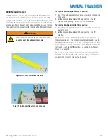
All Vigilant
®
transfer switch mechanisms incorporate a double-
throw action switching device for automatic transferring. The
Vigilant
®
transfer switch mechanism is a contactor-operated
device controlled by a set of utility and generator solenoids.
Manual operation is also provided for manual transfer of the load
between the power sources if necessary.
Figure 2 – Vigilant
®
Series
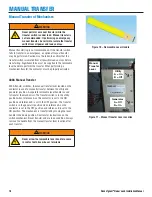
Receiving, Handling and Storage
Shipment contents:
•
Vigilant
®
Series – Automatic Transfer Switch
•
Installation and User Manual
•
Warranty card
Receiving
Every effort is made to ensure that your Vigilant
®
transfer switch
arrives at its destination undamaged and ready for installation.
The packing is designed to protect the transfer switch’s internal
components as well as the enclosure. Care should be taken to
protect the equipment from impact at all times. Do not remove the
protective packaging until the equipment is at the installation site
and ready to be installed.
After unpacking, inspect the switch for any damage that may
have occurred during shipping. If any missing parts or damage is
discovered when unpacking, do not return the unit to the place of
purchase; please contact Ronk Electrical for instructions on how
to proceed. Never install a switch that has been damaged.
A shipping label affixed to the shipping box includes a variety of
product and shipping information, such as items and customer
numbers. Make certain that this information matches your order
information.
Handling
As previously mentioned, each Vigilant
®
transfer switch is
packaged in its own individual box. Protect the equipment from
impact at all times and do not double stack. Once the transfer
switch is at the installation site and ready to be installed, the
packaging material may be removed.
Storage
Although well packaged, this equipment is not suitable for
outdoor storage. If the transfer switch is to be stored indoors
for any period of time, it should be stored with its protective
packaging in place. Protect the transfer switch at all times
from excessive moisture, dirty conditions, corrosive conditions
and other contaminants. It is strongly recommended that the
package-protected equipment be stored in a climate-controlled
environment of -4° to 149°F (-20° to 65°C), with a relative
humidity of 80% or less. Do not stack other equipment on top of
the stored switches.


