


12
Ronk Vigilant
®
Owner’s and Installation Manual
INSTALLATION AND WIRING
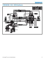
Power Connections
Proper power cables need to be installed to the transfer switch and
should be installed by licensed electrical contractors. Improper instal-
lation or connections of these power cables are extremely dangerous
and may cause severe injury or death. All power connections are to
be connected to the proper lugs, which are included on the switch
contactor and neutral block assembly. Connect the utility, generator,
neutral and load cables to the terminals, which are clearly marked
on the transfer switch
(see Figure 5)
. Verify that all connections
are correct before tightening lugs. All power cable lug connections
must be tightened to the proper torque values as shown in
Table 1.
!
WARNING
Low-voltage wire cannot be installed in the same
conduit as power voltage wiring. It could result
in shock due to short circuit as well as cause
electromagnetic interference resulting in
non-operation of the system.
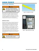
Utility Cable
Lugs
Generator
Cable Lugs
Load Cable
Lugs
Neutral
Lugs
Figure 4 – Power Cable Connection Locations
!
WARNING
On 600A models, always install the transparent
protective shields covering the power
connections of the switch mechanism once the
proper connections are performed.
Lug Torque Values
Table 1: 400-600A Lug Torque Values
Internal Socket Size Across Flats
Tightening Torque
1/2 in. (13 mm)
500 in-lb (56 N·m)
Wire size range 4 to 600 MCM copper using Ilsco lug # TA-500-S
for 400A systems
Wire size range 2 to 600 MCM copper using Ilsco lug # PB2-600
for 600A systems
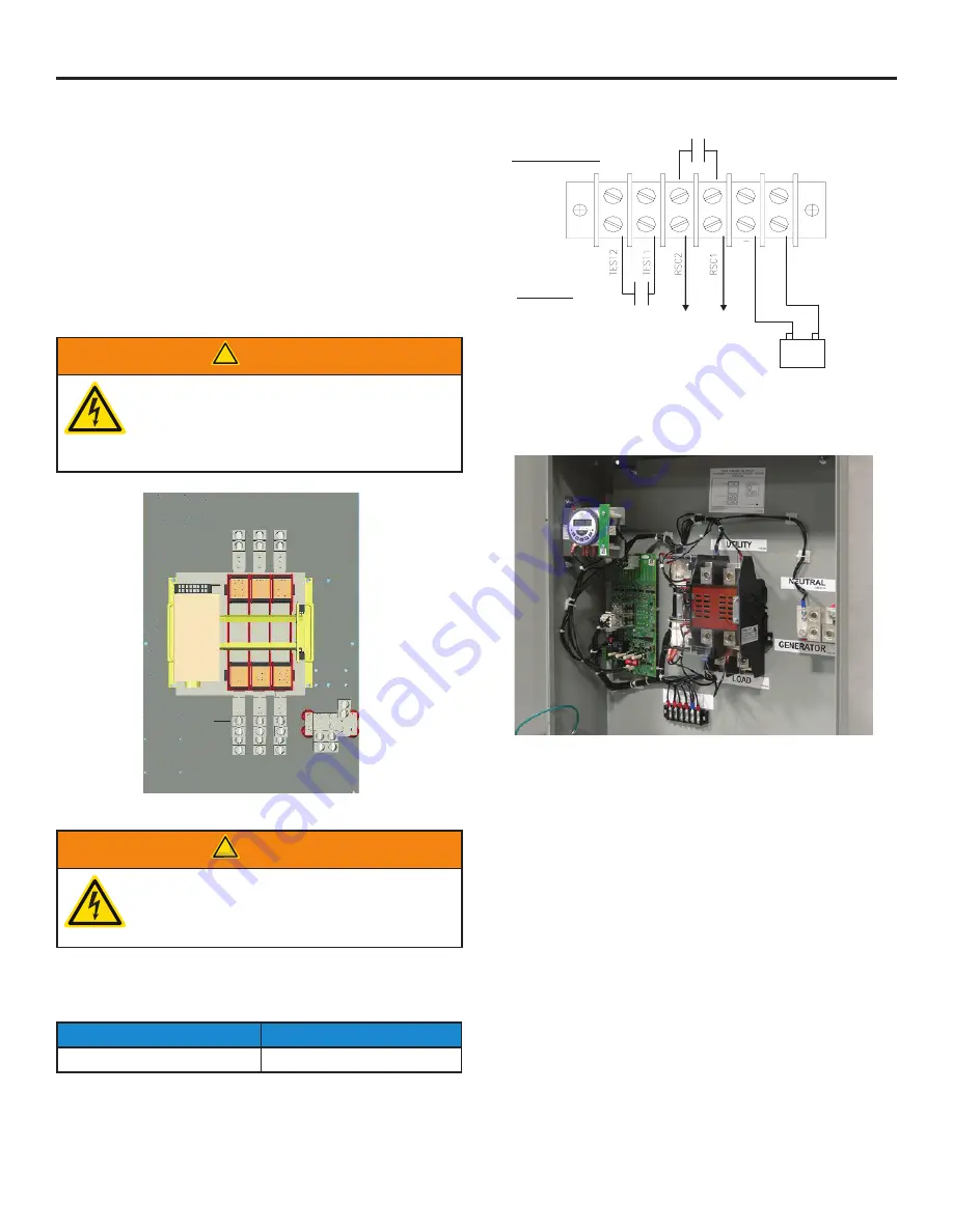
Connections
Ba
tter
y
+
Ba
tter
y
-
Transfer Switch
(Internal)
Generator
SPST
(Optional)
12/24VDC
+
-
N.O. dry contacts
Remote Start
Contacts
–
To
Generator
Generator Battery
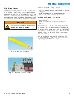
Figure 5
Figure 6
OTE:
N
The transfer switch consists of the 6-position terminal
block (shown in Figure 6) for connections.
B
and
Battery –
must be connected for operation of the
control board. The battery is either 12V DC or 24V DC. A 1A fuse
should be placed on the B connection. Do not use an
isolated power supply to power the controller as the controller
requires a reference to neutral for AC sensing, which it obtains
from the distribution system via Battery -.
RSC1
and
RSC2
need to be connected to the remote start/stop
connections of the generator to allow automatic starting. These
are N.O. dry contacts.
An optional customer-supplied test switch may be installed by the
customer using the
TEST 1
and
TEST 2
terminals. A closed circuit
between the test connections will simulate a utility failure. See
wiring diagram for details.
The battery charger needs to be of high quality. Low-quality
battery chargers will often go into full recharge mode due to
control board current draw. This will quickly wear out the battery.


