background image


18 


1.


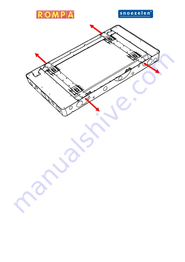
Unscrew the 4x M4 screws which secure the 2x brackets to the 
panels. The brackets are secured to avoid any damage during transit. 
 
Be sure to place the 4x M4 screws in a safe place as they will be 
required later. 
 

2.


Remove the brackets from the panel by sliding the bracket down and 
then lift them out of panel. 
 
Place the brackets safely to one side as they will be required later. 

Summary of Contents for SNOEZELEN Colour Catch Combo

Page 1: ...Colour Catch Combo 22873 September 2018 Copyright ROMPA Ltd Colour Catch Combo Instruction Manual...

Page 2: ...l Specification Dimensions Contents 7 Compatible Rompa Products 7 Operation 7 Modes 10 Touch Screen 12 Illuminated Push Buttons 14 External Switches 14 15 Microphone Input Rompa Wireless Operation 16...

Page 3: ...3 Panel Overview front...

Page 4: ...4 Panel Overview back...

Page 5: ...ophone but most of all to be great fun The panel fills with colour and light during use and provides exciting visual and auditory rewards for taking part Matching is an important foundation skill for...

Page 6: ...6 Dimensions All dimensions in mm Contents 1x Colour Catch Combo 2x Wall Mounting Bracket 4x M4 Screws screwed on sides 1x UK Mains Lead 1x US Mains Lead 1x EU Mains Lead...

Page 7: ...shion Wall Mat Operation Modes The mode dictates how the panel behaves The Colour Catch Combo has 4 modes which can be selected via the touch screen and an additional mode when a microphone is plugged...

Page 8: ...The squares will then extinguish and the user will have press the corresponding coloured Illuminated push buttons from memory this may require the user to press the same coloured push button more tha...

Page 9: ...icrophone has been detected The mode and brightness of the panel cannot be adjusted via the touchscreen whilst a microphone is plugged in The panel will display two colours The size location and the s...

Page 10: ...reen Brightness 100 Panel Brightness 100 Sound Effects On WiFi On Lock Off Mode Press the light blue mode button to cycle through the modes of the panel Press the red forward or back buttons to cycle...

Page 11: ...the illuminated push buttons Press the red forward or back buttons to cycle through the other menu options Touch Screen Brightness Pressing the yellow screen brightness button will cycle the panel th...

Page 12: ...ond to other Rompa compatible wireless products With wireless turned off it will ignore Rompa compatible wireless products Press the red forward or back buttons to cycle through the other menu options...

Page 13: ...uced and the buttons are unresponsive when locked Red Select Red via the Red illuminated push button or an external switch plugged into the Red input jack Green Select Green via the Green illuminated...

Page 14: ...panel has 1 microphone input To use a microphone with the panel simply plug a microphone into the 6 35mm jack located in the bottom right of the panel When the microphone is inserted the panel will a...

Page 15: ...or a button on the panel is pressed to return the panel to its previous mode Pressing the central function button turns the panel screen multi coloured The panel will remain this colour unless a new...

Page 16: ...n the mains plug and or power switch for the Panel is easily accessible to facilitate removal of power Due to the size of the product it is recommended that it is installed by two people Recommended T...

Page 17: ...17 All dimensions in mm...

Page 18: ...secured to avoid any damage during transit Be sure to place the 4x M4 screws in a safe place as they will be required later 2 Remove the brackets from the panel by sliding the bracket down and then li...

Page 19: ...here you would like it to be mounted ensuring it is level Whilst in position mark where the centre of the bracket mounting holes are on the wall Do this for all 4x bracket mounting holes Place the pan...

Page 20: ...t it level when mounting it to the wall The top bracket mounting holes should line up with the top 2x marks and the bottom bracket mounting holes should line up with the bottom 2x marks Fasteners are...

Page 21: ...hilst mounting the brackets Place the panel on the brackets To do this have the panel slightly higher than its final resting position When you feel the panel has slotted into the bracket gradually low...

Page 22: ...primary user and whether they should be seated or standing should dictate the height at which the panel is mounted Operation Panel must always be used under supervision Do not strike the panel The pa...

Page 23: ...ohol is recommended for more stubborn stains Ensure the panel does not become wet Particular care should be taken around apertures in the chassis and any electronics touch screen power button illumina...

Page 24: ...k on This will reset the panel settings and revert the panel buttons to unlock If troubleshooting does not solve the issue please contact Rompa Customer Services 44 0 1246 211 777 External Switch Unre...

Reviews: