background image

21

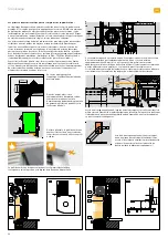
For thermal insulation composite systems, elements need to be insulated with a 

thickness of approx. 40 mm using stepped profiles. If this is not possible, appropri-

ate measures must be taken to reduce the risk of fissures appearing in the render. 

Ideally, this is done from the outset in agreement with a building professional and 

in coordination with the planners as this potentially has a big impact on the overall 

planning and building process.


At the installation stage, before rendering, the area between the cover frame and 

the guide rail needs to be sealed to meet the same resistance-to-driving-rain class 

as required by the window. This can be done using sealing tape or foil, an appropri-

ate rail, or other appropriate arrangements.

At the installation stage, before rendering, it must 

be ensured that rainwater drains off onto the win-

dow sill. Ideally, the edge profile is notched and 

the rails run down to the window sill (be aware of 

lengthwise expansion!).

The following points must be considered when planning:

After successful installation, the plaster baseboard should be rendered within 

three months. In the event that rendering is not performed within three months, 

Roma recommends weather-protecting the Styrodur boards using appropriate 

means (however, do not seal airtight). Danger of overheating! Please also note that 

depending on the installation location, rendering the Styrodur boards directly may 

not be possible. In this case, please read the following instructions:

The following information is a short summary of the most important points that 

you will find described and illustrated in current German guidelines and guidance 

documents (such as the guidelines for joints between windows and roller shutter, 

venetian blind or textile screen boxes on render, thermal insulation composite 

systems or dry constructions (= „GemRi“ joint guideline or the rendering guideline); 

the windowsill guidelines – for installing a windowsill in thermal insulation composite 

system façades and rendered façades, as well as suspended façades; RAL-Montage 

guidance documents; and TR105 published by the BVRS):

To avoid fissures forming in the render, the boxes should be tightly secured in place 

to prevent them from moving. Foam filling can be used on the sides. However, non-

expanding foam should be used to avoid damaging any elements. Please ensure 

that no foam gets onto the controls or penetrates inside the box. 

If a box is installed after rendering, it should be mounted using a sealing Kompri 

band on interstices.


Where different elements join together, 

in addition to placing reinforcement 

fabric vertically and horizontally, it can 

also be placed diagonally for extra 

strength to provide optimum protection 

against fissuring. 


As a rule, the box’s bottom profile 

cannot be used as a render edge and 

needs to be decoupled from the render 

using a clip-on profile. 

Additionally, it should not extend into the render and needs to be notched as per 

the position and width of the installed fabric guide rail.

275

275

270

1 mm

8 mm

12 mm

20,6 mm

275

270

270

275

275

270

270

275

275

275

270

1 mm

8 mm

12 mm

20,6 mm

275

270

270

275

275

270

270

275

275

275

270

1 mm

8 mm

12 mm

20,6 mm

275

270

270

275

275

270

270

275

275

275

270

1 mm

8 mm

12 mm

20,6 mm

275

270

270

275

275

270

270

275

TD

01366

Fensterbank

Fensterelement

Mauerwerk

Mauerwerk

Fensterelement

XP-Zusatz-
befestigung
nach Erfordernis

Tropfkante
APU-Aufsteckprofil

24.09.2015

Kastenprofil
INTEGO.XP

B259.XP

INTEGO.XP

Rollladenanschluss bei Mauerwerk mit Wärmedämm-Verbundsystem,
Kasten verputzt, mit Sturz.

1

Schnitt 1-1

INTEGO.XP
Kastengrösse 138

Kasten -
Abschlusswinkel

Führungsschiene
P-XP-DiFS 53x42

Führungsschiene
P-XP-DiFS 53x42

Dichtebene
Schlagregendicht

Armierung mit
Glasfasergewebe

Decke

Sturz

Das schematisch dargestellte Detail ist als unverbindlicher Lösungsvorschlag zu sehen.
Die Schlagregendichtheit wird zwischen Fenster und Baukörper hergestellt.
WDV-System nach Herstellerangaben.

1

Putzträgerplatte
20mm, vollflächig mit 
WDVS verklebt und 
Zusatzbefestigung.
Überstand seitlich
über Leibungskante
min. 15cm 

Putzträgerplatte
20mm, vollflächig mit 
WDVS verklebt und 
Zusatzbefestigung.
Überstand seitlich
über Leibungskante
min. 15cm 

Dichtebene
Schlagregendicht

1:5

Stand

Aussenputz

Klebemasse

Index

Detail Nr.

Masstab

ROMA KG

Dämmung
WdVs

ma

x.

TD

02586

Fensterbank

Fensterelement

Mauerwerk

Mauerwerk

Fensterelement

XP-Zusatz-
befestigung
nach Erfordernis

Tropfkante
APU-Aufsteckprofil

24.09.2015

Kastenprofil
INTEGO.XP

B259.XP

INTEGO.XP

Rollladenanschluss bei Mauerwerk mit Wärmedämm-Verbundsystem,
Kasten verputzt, mit Sturz.

1

Schnitt 1-1

INTEGO.XP
Kastengrösse 138

Kasten -
Abschlusswinkel

Führungsschiene
P-XP-DiFS 53x42

Führungsschiene
P-XP-DiFS 53x42

Dichtebene
Schlagregendicht

Armierung mit
Glasfasergewebe

Decke

Sturz

Das schematisch dargestellte Detail ist als unverbindlicher Lösungsvorschlag zu sehen.
Die Schlagregendichtheit wird zwischen Fenster und Baukörper hergestellt.
WDV-System nach Herstellerangaben.

1

Putzträgerplatte
20mm, vollflächig mit 
WDVS verklebt und 
Zusatzbefestigung.
Überstand seitlich
über Leibungskante
min. 15cm 

Putzträgerplatte
20mm, vollflächig mit 
WDVS verklebt und 
Zusatzbefestigung.
Überstand seitlich
über Leibungskante
min. 15cm 

Dichtebene
Schlagregendicht

1:5

Stand

Aussenputz

Klebemasse

Index

Detail Nr.

Masstab

ROMA KG

Dämmung
WdVs

ma

x.

TD

01

45

7

[


EN ]

Plastering

200 mm

20

0 m

m

Summary of Contents for PURO 2.XR-RS

Page 1: ...1 PURO 2 XR RS PURO 2 XRK RS Montageanleitung Assembly instruction Instructions de montage Montagehandleiding ...

Page 2: ...1200 mm 4 x 1201 1650 mm 5 x 1651 2100 mm 6 x 2101 2800 mm 7 x 2801 3400 mm 8 x 3401 4000 mm 9 x 4001 4500 mm 10 x TD02097 16 mm DE Montagehilfe EN Assembling aid FR Aide de montage NL Montagehulp TD02227 y 100 mm 100 mm ...

Page 3: ...omprimeerde band DE Kompriband EN compressed tape FR joint de compression NL gecomprimeerde band C D DE Montagehilfe EN Assembling aid FR Aide de montage NL Montagehulp A B TD02026 TD02072 TD02028 TD01898 TD02512 TD01899 TD01897 TD02530 TD02028 TD02511 12 12 TD02072 ...

Page 4: ...4 1 1 1 2 TD02049 TD01890 TD02050 TD02338 TD02420 5 0 TD02076 DE drücken EN push FR presser NL pers 1 2 TD02054 TD02055 DE drücken EN push FR presser NL pers opt TD02227 2 0 3 0 4 0 ...

Page 5: ...5 TD02400 6 0 A1 6 0 A2 7 0 A2 opt TD02398 TD02400 TD02060 TD02399 1 1 2 2 TD02032 TD02032 DE außen EN outside FR extérieur NL buiten 1 2 KLICK 1 2 TD02356 ...

Page 6: ... opt opt opt opt DE Führungsschiene eingerückt EN Guide rail engaged FR Coulisses rentrées NL Geleider geplaatst DE Führungsschiene eingerückt EN Guide rail engaged FR Coulisses rentrées NL Geleider geplaatst TD02402 TD02403 TD02403 TD02404 KLICK ...

Page 7: ...7 TD02405 TD02406 1 2 TD02416 1 2 DE Montage Führungsschiene 33 x 81 EN Assembly Guide rail 33 x 81 FR Montage Coulisse 33 x 81 NL Montage Geleider 33 x 81 10 0 11 1 11 2 ...

Page 8: ...12 1 13 1 DE Mögliche Torx Klingen Torx Klinge lang Schaft E 6 3 TX20 150 6 mm Klinge Torx TX20 GARANT 8 mm Klinge Torx TX20 GARANT EN Possible torx blades torx blade long shaft E 6 3 TX20 150 6 mm blade torx TX20 GARANT 8 mm blade torx TX20 GARANT FR Possibilités de clé Torx clé Torx tige E 6 3 TX20 150 clé de 6 mm Torx TX20 GARANT clé de 8 mm Torx TX20 GARANT NL Beschikbare Torx schroeven Torx s...

Page 9: ... binnen DE Außen EN outside FR extérieur NL buiten DE Schiene einklipsen EN clip in guide rails FR Cliquer les coulisses NL Kunststof geleiders inklipsen DE Höhe Anschlagklotz einstellen EN adjust height of stop block FR Ajuster en hauteur le bloc de butée NL Aluminium montagesteunen op hoogte stellen DE Inbusschraube anziehen EN tighten socket screw FR Serrer la vis hexagonale NL Inbusschroeven v...

Page 10: ...10 130 click click 2 0 1 0 4 0 3 0 5 1 5 2 5 3 KLICK ...

Page 11: ... DE Probelauf EN Test run FR Test NL Testrun TD02418 TD02419 TD02850 TD02851 TD02853 17 0 18 0 19 1 19 2 20 0 21 0 22 0 DE Besonderheiten bei vorgesetzter Montage EN Special assembly in case of forward offset FR Montage décalé vers l avant NL Naar voren geplaatste montage 1 1 2 2 KLICK TD02854 TD02853 ...

Page 12: ...as on the interior FR Décrochage du caisson pour les longueurs larges Pour les éléments larges nous vous recommandons de décrocher le caisson sur le chantier afin d éviter une compression trop impor tante de la mousse ou du matériel dans le milieu de l élément Le décrochage peut s effectuer sur la face extérieure ou intérieure selon les besoins NL Bevestigen of ophangen van kasten bij grote maten ...

Page 13: ...15 kg Maximale spanning 250 N 25 kg TD01428 1 2 TD01428 24 5 DE bei Bedarf Seil kürzen EN cut rope if necessary FR raccourcir le câble si nécessaire NL indien nodig staaldraad inkorten DE Hinweis Die Seile werden senkrecht nach unten geführt EN Note The ropes will be mounted vertically FR Remarque les câbles sont guidés verticalement vers le bas NL Let op De staaldraden worden verticaal gemonteerd...

Page 14: ... the support clamps and turn it towards the rear The second catch is released Astuce saisissez des deux mains la pièce de centrage directement à côté du collier de support et tournez la vers l arrière Le deuxième cran sera ainsi déverrouillé Tip met beide handen die koplijst direct naast de klem vastpakken en naar achter draaien De tweede vergrendeling komt los DE Schlitzschraubendreher EN Flat he...

Page 15: ...17 17 17 17 1500 17 17 17 17 17 17 17 2000 17 17 17 17 17 17 17 2500 17 17 17 17 17 17 17 3000 17 17 17 17 17 17 17 3500 17 17 17 17 17 17 17 4000 17 17 17 17 17 17 17 4500 17 17 17 17 17 17 13 5000 GL windstabil Windgrenzwerte in m s Höhe bis Breite bis 1000 1500 2000 2500 3000 3500 4000 4500 5000 1000 20 20 18 18 18 1500 20 20 18 18 18 2000 20 20 18 18 18 2500 20 20 18 18 18 3000 20 20 18 18 18 ...

Page 16: ...s gilt bei Nichtbeachtung der für die Einbaubedin gungen notwendigen Windwiderstandsklasse der Elemente Des Weiteren muss der Montageuntergrund eben waagerecht und parallel zueinander sein Falls dies nicht der Fall ist müssen geeignete Ausgleichs maßnahmen getroffen werden Für Mängel die aus unzureichender Befestigung ungeeignetem Befesti gungsmaterial oder aus nicht ausreichend stabilem Baukörper...

Page 17: ... or severe injury danger of falling The same also applies if installation instructions concerning the wind resistance class of elements are not observed In addition the mounting substructure needs to be even level and parallel If this is not the case the appropriate compensatory measures need to be taken ROMA may not be held liable for any defects resulting from improper installation inappropriate...

Page 18: ... de chute Il en est de même pour le non respect des charges de résistance au vent inhérentes au montage de l élément Le support de montage doit être plane horizontal et parallèle l un par rapport à l autre Le cas échéant il convient de prendre les mesures de compensation nécessaires ROMA se dégage de toute responsabilité en cas de manques liés à une fixation insuffisante un matériel de fixation in...

Page 19: ... geval worden gevolgd Het niet naleven ervan kan ernstige gevolgen hebben valgevaar Hetzelfde geldt voor het niet naleven van de windbestendigheidsklasse die vereist is voor de installatie Verder moet het montageoppervlak horizontaal vlak en evenwijdig aan elkaar zijn Als dat niet het geval is moeten passende compenserende maat regelen worden genomen Roma biedt geen garantie voor gebreken als gevo...

Page 20: ...itfaden TR105 des BVRS Zur Vermeidung von Putzrissen darf sich der Kasten nicht bewegen und muss gegebenenfalls zusätzlich befestigt werden Ein Ausschäumen seitlich ist möglich allerdings muss dann mit nicht drückendem Schaum gearbeitet werden um Beschädigungen am Element zu vermeiden Bitte darauf achten dass kein Schaum an die Bedienelemente oder in den Kasteninnenraum dringen kann Wird der Kaste...

Page 21: ...as well as suspended façades RAL Montage guidance documents and TR105 published by the BVRS To avoid fissures forming in the render the boxes should be tightly secured in place to prevent them from moving Foam filling can be used on the sides However non expanding foam should be used to avoid damaging any elements Please ensure that no foam gets onto the controls or penetrates inside the box If a ...

Page 22: ...par l extérieur et dans des façades mur rideau Guide de pose RAL TR105 de la Fédération de l industrie allemande pour les volets roulants et les protections solaires Pour éviter les fissures dans le crépi le caisson ne doit pas bouger et une fixation additionnelle peut être nécessaire Un remplissage de mousse est possible sur le côté en prenant soin d utiliser une mousse extensible pour éviter l e...

Page 23: ...m en gestucte gevels RAL montagevoorschriften TR105 gepubliceerd door de BVRS Om scheurvorming in het stucwerk te voorkomen moet de kast vast op zijn plaats zitten en eventueel extra worden vastgezet Schuimvulling aan weerskanten van de kap kan worden gebruikt gebruikt schuim wat niet uitzet om beschadigingen aan het element te voorkomen Zorg ervoor dat er geen schuim op bedieningsele menten of in...

Page 24: ... 85 09 info roma france fr www roma france fr ROMA Benelux b v Campagneweg 9 4761 RM Zevenbergen T 31 0 168 405259 F 31 0 848321889 info romabenelux nl www romabenelux nl Technische Änderungen vorbehalten Keine Haftung für Druckfehler Technological changes excepted ROMA assumes no liability for errata Sous réserve de modifications techniques Aucune responsabilité en cas de fautes d impression Tech...

Reviews: