background image


PDP TV Service Manual 

Hisense confidential 

Product Safety Servicing Guidelines


1.


Safety precautions


WARNING: 

Service should not be attempted by anyone unfamiliar with the necessary precaution on this 
receiver. The following are the necessary precautions to be observed before servicing this 
chassis. 
1. When replacing a chassis in the cabinet, always be certain that all the protective devices are put 
back in place, such as: non-metallic control knobs, insulating covers, shields, isolation 
resistor-capacitor network etc. 
2. When replacing parts or circuit boards, disconnect the power cord. 
3. When replacing a high wattage resistor (oxide metal film resistor) on the circuit board, keep the 
resistor 10mm (1/2in) away from circuit board. 
4. Connection wires must be kept away from components with high voltage or high temperature. 
5. If any fuse in this TV receiver is blown, replace it with the FUSE specified in the chassis parts 
list. 

2.Product Safety notice 


Many electrical and mechanical parts in the chassis have special safety-related characteristics. 
 
These characteristics are often passed unnoticed by a visual inspection. 
Replacement parts, which have these special safety characteristic are identified in this manual 
and its supplement electrical components having such features are shaded on the schematic 
diagram and the parts list. 
 
Before replacing any of these components, read the parts list in this manual carefully. The use of 
substitute replacement parts, which do not have the same characteristic as specified in the parts 
list may create shock, fire or other hazards. 


NOTES


Screen Image retention

   Do not display a still image (such as on a video game or when 

hooking up a PC to this PDP) on plasma monitor panel for a long time as it can cause screen 
image retention. This image retention is also known as “screen burn”. To avoid such image 
retention, reduce the degree of brightness and contrast of the screen when displaying a still 
image. 

A still image displayed too long may cause permanent damage to the PDP Panel


Watching the PDP TV in 4:3 format or other non full screen formats for a long period of time may 
leave traces of borders displayed on the left, right and centre of the screen caused by the 
difference of light emission on the screen. Playing a DVD or a game console may cause similar 
effect to the screen. Damages caused by the above effect are not covered by the Warranty. 

Afterimage on the Screen

      Displaying still images from Video games and PC for longer than a 

certain period of time may produce partial afterimages. To prevent this effect, reduce the 
brightness and contrast when displaying still images for a long time. 

Height

      The PDP can normally operate only under 2000m in height. It might abnormally function 

at a place over 2000m in height and do not install and operate there. 

Avoid operating the TV at temperatures below 5

(41°F) 

Warranty

 Warranty does not cover any damage caused by image retention; Burn-in is not covered 

by the warranty. 

CAUTION: BEFORE SERVICING THE CHASSIS, READ THE “SAFETY 

PRECAUTION” “PRODUCT SAFETY NOTICE”ON PAGE 3 OF 
THIS MANUAL. 

Summary of Contents for RP-42H10

Page 1: ...PDP TV Service Manual 1 Plasma display television Service Manual Classis MST9 Product Type RP 42H10 Ver 1 0 Rolsen...

Page 2: ...General description 7 3 2 Panel block diagram 8 3 3 Power PSU description 8 3 4 Power block diagram 9 4 Block Diagram 10 4 1 unite sketch map 10 4 2 Video processing diagram 13 4 3 Audio processing d...

Page 3: ...te replacement parts which do not have the same characteristic as specified in the parts list may create shock fire or other hazards NOTES Screen Image retention Do not display a still image such as o...

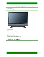
Page 4: ...U product function High end flat display HDMI input High definition compatible Wide Screen display optimized for cinema viewing Multimedia display TV PC High clear picture Audio equalizer Color enhanc...

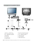
Page 5: ...PC YP P Audio input B R Volume decrease Left button Volume increase Right button Previous channel Down button Next channel Up button 11 10 9 13 12 6 5 4 3 2 1 8 7 IR angle for the remote control scree...

Page 6: ...68 YPBPR 50Hz 576p 720p 1080i YPBPR 60Hz 480p 720p 1080i Static contrast ratio 40 1 Brightness 400 cd m Viewing angle 140 H V Power source AC 100V 240V 50 60Hz Power consumption 300W Audio output 2 x...

Page 7: ...PDP TV Service Manual Hisense confidential 7 PDP panel spec 1 General description...

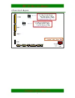
Page 8: ...PDP TV Service Manual Hisense confidential 8 2 Panel block diagram 3 Power PSU description Standard Voltage Range AC 100V 240V Available Voltage Range AC 90V 265V Frequency Range 50Hz 60Hz 5Hz...

Page 9: ...1 CN809 CN801 CN804 Vs Voltage Variabe Resistor Turn right increase Voltage Turn left decrease Voltage Shipment Condition 185V VR901 VS VR951 VA Va Voltage Variable Resistor Turn right increase Voltag...

Page 10: ...is composed by the main board The main chip for video decoder is MST9E88L produced by MSTAR co ltd 1 unite sketch map XPK01 KEY BOARD 970A XP25 XP26 XP24 XP3 J20 XP10 XP7 XP31 MAIN BOARD 961A SCART BO...

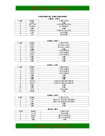
Page 11: ...V POWER 5 5VSC 5V POWER 6 5VSC 5V POWER 7 GND GND 8 GND GND 9 GND GND CN803 XP7 ITEM NAME FUNCTION 1 5VSC 5V POWER 2 5VSC 5V POWER 3 5VSC 5V POWER 4 GND GND 5 GND GND 6 GND GND 7 12VSC power for ampli...

Page 12: ...3 LEDR LED CONTROL 4 GND GND 5 5VST_B POWER OF REMOTE 6 GND GND XP1 XP31 ITEM NAME FUNCTION 1 AV1 SCART2 _Y SIGNAL 2 GND GND 3 A C SCART2_C SIGNAL 4 S PI8 SCART2 FUNCTION SELECT 5 A L SCART2 AUDIO IN_...

Page 13: ...13 2 Video processing diagram YPBPR VIDEO OUTPUT VIDEO S VIDEO SCART1 _CVBS SCART1_ RGB SCART2 _CVBS HDMI PC PDP module PDP42S1 CPU MST 9E88L SAW FILTER HS9455 HS6274 IF TDA9886 TUNER TDQ 6FT W 116H F...

Page 14: ...ress on the MENU key 2 Select the sub menu SOUND with CH CH 3 Select the parameter BALANCE with the keys VOL VOL 4 Press a series of numbers 0 5 3 2 quickly SERVICE MODE MENU includes Fac Menu CPU MST...

Page 15: ...Color Temp Standard RED COLOR 126 GREEN COLOR 128 BLUE COLOR 135 White Balance R DRV 10 G DRV 9 B DRV 12 R CUT 126 G CUT 128 B CUT 135 BRIGHT_H 80 CONTRAST _H 80 BRIGHT_L 40 CONTRAST_L 40 Factory Men...

Page 16: ...S1 852 480 FLASH PS25LV040 Test Pattern BLUE Factory Init QingDao HuangDao Guiyang Hungary France Austria CLEAR PROTECTLY CLEAR UNPROTECTLY Option SOURCE TV BRIGHT 0 10 BRIGHT 50 100 BRIGHT 100 145 CO...

Page 17: ...z 12 500Hz 10 1 5KHz 11 5KHz 8 10KHz 15 Music 120Hz 19 500Hz 11 1 5KHz 12 5KHz 14 10KHz 20 Speech 120Hz 4 500Hz 10 1 5KHz 12 5KHz 7 10KHz 5 Picture Mode Standard Brightness 50 Contrast 50 Colour 50 Br...

Page 18: ...tings data Please do not tell user the purpose password Software updating PDP4235EU software updating 1 You can update the software through a special tool show as below 2 Software Updating Operation 1...

Page 19: ...TV Service Manual Hisense confidential 19 2 Set the ISP_TOOL4 0 9 only for the first time update DLPORTIO dll and FTD2XX DLL must be in the same folder 1 Find the folder where the ISP_TOOL4 0 9 lies...

Page 20: ...e DLPORTIO dll and FTD2XX DLL must be in the same folder 2 Double click the ISP_TOOL4 0 9 icon and then a dialog will show as below 3 Click the Config button And then a dialog will show as below You s...

Page 21: ...PDP TV Service Manual Hisense confidential 21...

Page 22: ...PDP TV Service Manual Hisense confidential 22...

Page 23: ...you have finished all above you should click the Apply button to complete the configuration 3 Turn on the TV then we can update 4 Double click the ISP_TOOL4 0 9 icon and then a dialog will show as bel...

Page 24: ...PDP TV Service Manual Hisense confidential 24 6 Find the update file in your computer...

Page 25: ...PDP TV Service Manual Hisense confidential 25 7 Double click the update file A dialog will show as below...

Page 26: ...PDP TV Service Manual Hisense confidential 26 8 Click the Auto button And then do as shown below...

Page 27: ...PDP TV Service Manual Hisense confidential 27 9 Click the Connect button And then do as shown below...

Page 28: ...PDP TV Service Manual Hisense confidential 28 10 Click the Run button 11 When the update is finished a dialog will show as below...

Page 29: ...PDP TV Service Manual Hisense confidential 29 PDP4235EU Explode View and Bom Spare Parts List Main Spare Parts Name Type Part No 1 2 3 4 5 6 7 8 9 10 11...

Page 30: ...iver Board connections blue red Press power on the remote to quit stand by mode No problem OSD Check main board connections or change main board Check LVDS connection or module connections ok no Press...

Page 31: ...Press MENU to display menu on the screen TV audio ok no Press mute button no ok No problem Check other channel ok no Check TV channel input part circuit diagram Check audio board connections or chang...

Page 32: ...e TV The LED is blue but no picture or and no sound You should to replace the main board 3 In TV state can not to tuning You should to replace the main board 4 No teletext You should to replace the ma...

Page 33: ...PDP TV Service Manual Hisense confidential 33 PDP Wall mounting Bracket Installation Guide READ CAREFULLY BEFORE INSTALLATION THE INSTALLATION GUIDE SHOULD BE RETAINED FOR FUTURE REFERENCE Caution...

Page 34: ...heater or humidifier below the installed TV 9 The TV should be kept away from moisture sensors and power line The TV should be kept away from impact and vibration 10 Ensure that the power supply be d...

Page 35: ...l l M at eri al Q uant i t y N o nam e 3 1 360 0 2m m 480 0 5m m Wall mounting Quick Guide C B A A 6 5 4 2 0 B ol t M 8x45 bl ack F i xt ure di sk nam e N o Q uant i t y M at er i al 6 5 4 1 2 3 P l a...

Page 36: ...0uF C437 NC FB L78 100n C438 10uF C435 100n C436 FB L77 A6V 5V 3 3V 47uF C434 100n C433 STANDBY THEM_D 5Vstb_PDP VCCH VCCH 1 2 NC D23 12V NC 0R R482 PD3 INT1 1 PD4 XCK T0 2 GND1 3 VCC1 4 GND2 5 VCC2 6...

Page 37: ...0n C218 10u C251 10uH L42 3 3AVDD 100n C224 10u C253 10uH L44 3 3AVDD 390p C225 2 2u C254 10uH L45 100n C226 390p C227 100n C228 VDD_MPLL Vin 3 GND 1 Vout 2 AP1084K ADJ N22 100n C229 100u C255 100n C2...

Page 38: ...K R139 560p C92 AV2 Lin AV2 Rin 10K R126 12K R128 12K R127 560p C85 10K R129 560p C86 HD Lin HD Rin HD L HD R AV2 L AV2 R 3 2 1 STZ6 2N D53 AV3 10K R354 12K R357 12K R356 560p C351 10K R355 560p C350...

Page 39: ...37 75 R336 47 R339 0 1uF C311 NC 4 7K R333 NC 1 NC 2 NC 3 GND 4 SDA 5 SCL 6 VCLK 7 VCC 8 NC 24C02 U13 3 1 2 BAV99 D36 FB L54 5 10 4 9 3 8 2 7 1 15 14 13 12 11 6 0 0 VGA P3 3 1 2 BAV99 D35 75 R335 NC R...

Page 40: ...EC GND 17 5V POWER 18 HOT PLUG 19 101 101 102 102 103 103 104 104 HDMI_J P2 0 1uF C23 100 R39 NC 20K R50 NC 20K R49 10R R37 100 R38 NC R30 1K R43 1 2 5 6V D3 0 1uF C25 0 1uF C30 10R R36 0 R46 0 1uF C2...

Page 41: ...162 AD0 151 AD1 152 AD2 153 AD3 154 AD4 155 AD5 156 AD6 157 AD7 158 SIF0M 61 SIF0P 62 SIF1P 64 SIF1M 65 AUVRADN 67 AUVRADP 68 AUVREF 69 DQS1 100 MD15 101 GNDM 103 GNDM 131 VDDM 132 GNDM 145 VDDC 146...

Page 42: ...7 TOP 9 VIF1 1 VIF2 2 REF 15 NC 5 VAGC 6 16 DEEM 5 SCL 11 OUT1 3 NC 13 AUD_OUT 8 SDA 10 FMPLL 4 TAGC 14 AFD 6 SIOMAD 12 CVBS 17 AGND 18 VPLL 19 VPP 20 AFC 21 OUT2 22 SIF1 23 SIF2 24 TDA9885 6 U5 47UF...

Page 43: ...11 Y0 1 Y1 5 Y2 2 Y3 4 A 10 B 9 X 13 Y 3 VCC 16 GND 8 INH 6 VEE 7 NC 74HC4052 U3 22K R12 47K R24 NC 100pF C17 0R 10K R5 4 7K R27 10K R3 22K R14 0 1uF C2 6VBuf2 8VBUF 8V 8V 8VBUF PH R1out PH L1out A SW...

Page 44: ...SOT 23 1 3 2 NC 3904 V14 0 1uF C260 1nF C278 4 7K R289 1nF C277 47K R283 330nF C302 4 5 3 2 6 8 1 9 11 HEADPHONE XS5 4 7K R290 33K R280 1nF C282 1K R311 33K R278 100K R295 5 6 7 8 4 TL062 N11B 22 R316...

Page 45: ...16 5 18 7 20 9 11 12 15 17 19 21 2 4 6 8 10 13 SCART1 XS1 Scart2_Lout1 AV2_out1 Scart pin8 Scart2_Rout1 1 2 3 4 5 6 7 8 9 10 SCART2B XP1 Scart2_Rout1 Scart2_Lout1 AV2_out1 Scart pin8 AV1 C AV1 Y AV1_...

Page 46: ...IR in1 NC CR04 1 2 3 3904 V1 3 1 2 PNP T V2 LED R1 LED R1 5Vstb 100R RR04 100R RR03 SWK01 MENU KEY0 0 SWK02 SOURCE KEY0 0 4V SWK03 VOL KEY0 0 8V SWK04 VOL KEY1 0 SWK05 CH KEY1 0 4V SWK06 CH KEY1 0 8V...

Reviews: