background image

3

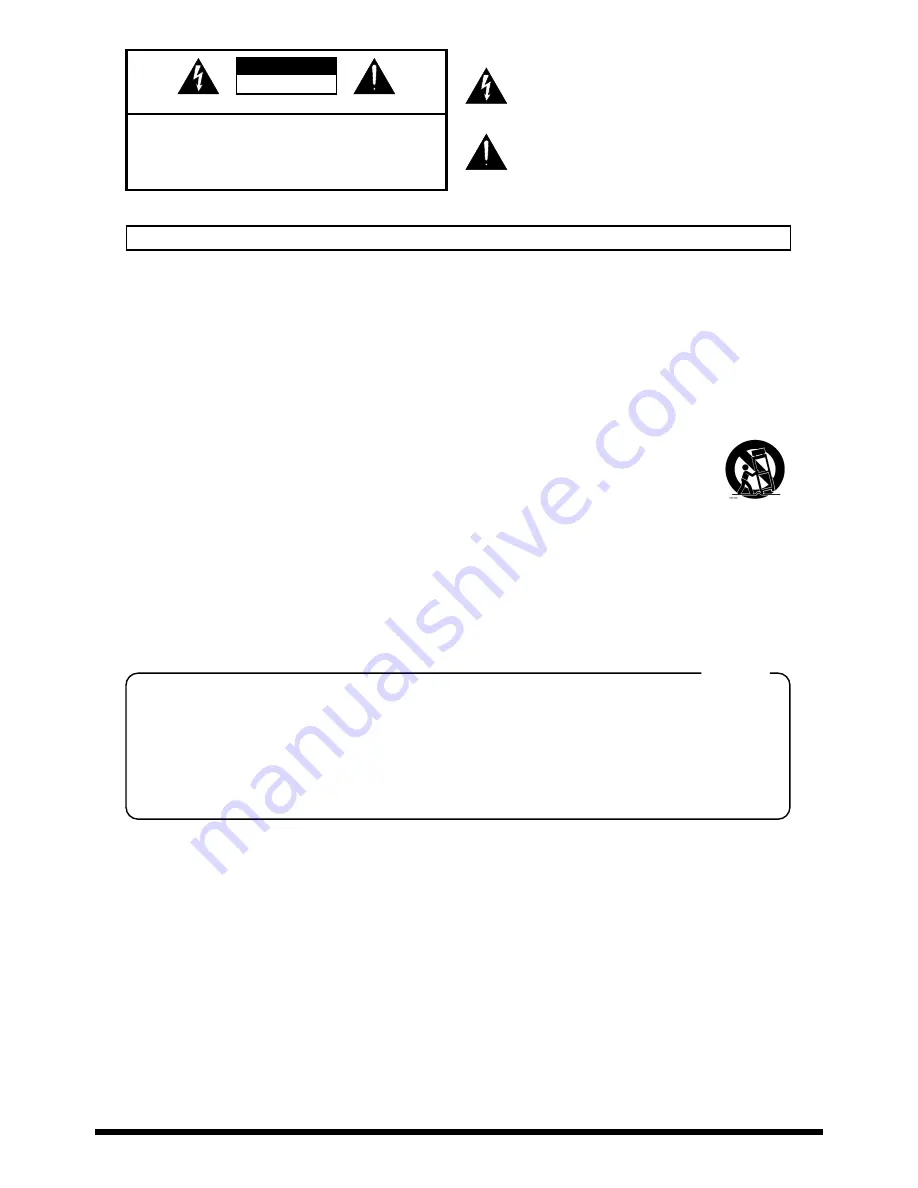
CAUTION

RISK OF ELECTRIC SHOCK

DO NOT OPEN

ATTENTION

: RISQUE DE CHOC ELECTRIQUE NE PAS OUVRIR

CAUTION:   TO REDUCE THE RISK OF ELECTRIC SHOCK,

DO NOT REMOVE COVER (OR BACK).

NO USER-SERVICEABLE PARTS INSIDE.

REFER SERVICING TO QUALIFIED SERVICE PERSONNEL.

The lightning flash with arrowhead symbol, within an 
equilateral triangle, is intended to alert the user to the 
presence of uninsulated “dangerous voltage” within the 
product’s enclosure that may be of sufficient magnitude to 
constitute a risk of electric shock to persons.

The exclamation point within an equilateral triangle is 
intended to alert the user to the presence of important 
operating and maintenance (servicing) instructions in the 
literature accompanying the product.

INSTRUCTIONS PERTAINING TO A RISK OF FIRE, ELECTRIC SHOCK, OR INJURY TO PERSONS.

IMPORTANT SAFETY INSTRUCTIONS

SAVE THESE INSTRUCTIONS

WARNING - When using electric products, basic precautions should always be followed, including the following:

1.

Read these instructions.

2.

Keep these instructions.

3.

Heed all warnings.

4.

Follow all instructions.

5.

Do not use this apparatus near water.

6.

Clean only with a damp cloth.

7.

Do not block any of the ventilation openings. Install in 
accordance with the manufacturers instructions.

8.

Do not install near any heat sources such as radiators, 
heat registers, stoves, or other apparatus (including 
amplifiers) that produce heat.

9.

Do not defeat the safety purpose of the polarized or 
grounding-type plug. A polarized plug has two blades with 
one wider than the other. A grounding type plug has two 
blades and a third grounding prong. The wide blade or the 
third prong are provided for your safety. When the provided 
plug does not fit into your outlet, consult an electrician for 
replacement of the obsolete outlet.

10. Protect the power cord from being walked on or pinched 

particularly at plugs, convenience receptacles, and the 
point where they exit from the apparatus.

11. Only use attachments/accessories specified by the 

manufacturer.

12. Never use with a cart, stand, tripod, bracket, 

or table except as specified by the 
manufacturer, or sold with the apparatus. 
When a cart is used, use caution when 
moving the cart/apparatus combination to 
avoid injury from tip-over.

13. Unplug this apparatus during lightning storms or when 

unused for long periods of time.

14. Refer all servicing to qualified service personnel. Servicing 

is required when the apparatus has been damaged in any 
way, such as power-supply cord or plug is damaged, liquid 
has been spilled or objects have fallen into the apparatus, 
the apparatus has been exposed to rain or moisture, does 
not operate normally, or has been dropped.

IMPORTANT: THE WIRES IN THIS MAINS LEAD ARE COLOURED IN ACCORDANCE WITH THE FOLLOWING CODE.

BLUE: 
BROWN: 

As the colours of the wires in the mains lead of this apparatus may not correspond with the coloured markings identifying 
the terminals in your plug, proceed as follows:
The wire which is coloured BLUE must be connected to the terminal which is marked with the letter N or coloured BLACK.
The wire which is coloured BROWN must be connected to the terminal which is marked with the letter L or coloured RED.
Under no circumstances must either of the above wires be connected to the earth terminal of a three pin plug.

NEUTRAL
LIVE

For the U.K.

Summary of Contents for Sound Canvas Digital SC-D70

Page 1: ...tten permission of ROLAND CORPORATION 201b Before using this unit carefully read the sections entitled IMPORTANT SAFETY INSTRUCTIONS Owner s manual p 3 USING THE UNIT SAFELY Owner s manual p 4 and IMPORTANT NOTES Owner s manual p 6 These sections provide important information concerning the proper operation of the unit Additionally in order to feel assured that you have gained a good grasp of ever...

Page 2: ......

Page 3: ...g has two blades and a third grounding prong The wide blade or the third prong are provided for your safety When the provided plug does not fit into your outlet consult an electrician for replacement of the obsolete outlet 10 Protect the power cord from being walked on or pinched particularly at plugs convenience receptacles and the point where they exit from the apparatus 11 Only use attachments ...

Page 4: ...e g flammable material coins pins or liquids of any kind water soft drinks etc to penetrate the unit 013 In households with small children an adult should provide supervision until the child is capable of following all the rules essential for the safe operation of the unit 014 Protect the unit from strong impact Do not drop it 015 Do not force the unit s power supply cord to share an outlet with a...

Page 5: ...ry to prevent cords and cables from becoming entangled Also all cords and cables should be placed so they are out of the reach of children 106 Never climb on top of nor place heavy objects on the unit 107b Never handle the power cord or its plugs with wet hands when plugging into or unplugging from an outlet or this unit 108a Before moving the unit disconnect the power plug from the outlet and pul...

Page 6: ... with a soft dry cloth 402 Never use benzine thinners alcohol or solvents of any kind to avoid the possibility of discoloration and or deformation Additional Precautions 553 Use a reasonable amount of care when using the unit s buttons sliders or other controls and when using its jacks and connectors Rough handling can lead to malfunctions 554 Never strike or apply strong pressure to the display 5...

Page 7: ...dio tracks 29 Playing the Internal Sound Generator 31 About the internal sound generator 31 Parts and sounds 31 Different types of parts 31 Which part receives the MIDI IN data 31 Selecting a part 31 Selecting basic sounds normal parts 32 Selecting a variation sound normal part 32 Using MIDI messages to switch sounds from another device or sequencer software 34 Selecting a drum set drum part 35 Us...

Page 8: ...tor You can enjoy ensemble performance using just a single SC D70 Only when the USB connector is used When the MIDI connectors are used a maximum of 16 parts are available Versatile and high quality sounds The SC D70 provides a versatile and high quality selection of 1 608 sounds and 63 drum sets These include the same sounds as the SC 55 55mkII SC 88 SC 88Pro and SC 8820 allowing you to enjoy you...

Page 9: ...dited and how effects should be handled have now been precisely defined Moreover the available sounds have been expanded General MIDI 2 compliant sound generators are capable of reliably playing back music files that carry either the General MIDI or General MIDI 2 logo In some cases the conventional form of General MIDI which does not include the new enhancements is referred to as General MIDI 1 a...

Page 10: ...tor simultaneously pressing DEC and INC will make the display window show the currently selected variation number Use this operation if you wish to change the variation number 6 Mic Guitar Input Jack A microphone or guitar can be connected to this jack 7 Mic Guitar Gain Select Switch Selects whether a microphone or a guitar is connected to the Mic guitar input jack MIC is selected when this switch...

Page 11: ...which the audio signal from the audio input jacks will be monitored through headphones or the like This knob will not affect the audio signal that is sent to the PC via USB i e the audio signal that is actually recorded 14 Headphone Jack A pair of headphones can be connected to this jack The output from this jack is the same as from the audio output 1 jacks fig 21 02 e_70 15 VOLUME Knob This knob ...

Page 12: ...cted to the computer via USB 20 MIDI Indicator This will light when the SC D70 receives MIDI messages 21 USB Recording Level Indicator This shows the output level of the audio signals sent from the USB connector to the computer 22 OUTPUT Level Indicator This shows the output level of the audio signal that is output from the rear panel audio output jacks and digital output connectors 19 20 18 21 22...

Page 13: ...audio device LINE OUT such as a CD player 3 Audio Output 1 Jacks Connect to these jacks when you wish to output audio signals to an audio device or amplifier speakers These jacks will always output DIGITAL and INST WAVE regardless of the recording source selection The output level of these jack is adjusted by the VOLUME knob fig 21 04 e_70 3 2 1 SC D70 LINE IN INPUT Powered Speaker etc Stereo set ...

Page 14: ...tical or coaxial It is not possible to use optical and coaxial simultaneously 8 Digital Input Connector Coaxial Connect a coaxial cable here if you wish to input a digital audio signal from an audio device such as CD MD DAT 9 Digital Output Connector Coaxial Connect a coaxial cable here if you wish to output a digital audio signal to a digital recorder such as an MD or DAT 10 USB Connector The SC ...

Page 15: ...ings About copyright Recording distribution sale lending public performance or broadcast in part or in whole of material musical compositions film broadcasts performances etc created by a third party is forbidden by law unless permission is obtained from the copyright holder Do not use this device for purposes that may infringe the copyrights of a third party Roland Corporation accepts no responsi...

Page 16: ...C position 3 Connect your microphone to the SC D70 s mic guitar input jack Your microphone is now connected To connect your audio equipment proceed to Connecting audio equipment p 18 To begin recording proceed to Selecting the recording source p 21 Microphone MIC 2 1 3 Lower position If the mic guitar gain select switch is in the GUITAR position when you are inputting from a microphone the sound w...

Page 17: ...gain select switch in the outward position to select GUITAR 3 Connect your guitar to the mic guitar input jack of the SC D70 Your guitar is now connected If you wish to connect audio equipment proceed to Connecting audio equipment p 18 If you wish to begin recording proceed to Selecting the recording source p 21 Electric Guitar GUITAR 2 1 3 Upper position ...

Page 18: ...re we will record stereo audio data e g from the output of an audio device into your sequencer software Making connections to the audio input jacks fig 22 03 e 1 Before you connect an audio device to the SC D70 lower the level of the audio input gain knob 2 Connect the audio input jacks of the SC D70 to the audio outputs of another audio device e g stereo set or CD player fig 22 04 e 1 SC D70 R L ...

Page 19: ...gital input output select switch to COAXIAL or OPTICAL fig 22 05 e_50 3 Connect the SC D70 s digital input connector to the digital output connector of the other audio device When using the OPTICAL connector fig 22 06 e When using the COAXIAL connector fig 22 07 e SC D70 DIGITAL OUT DIGITAL IN OPTICAL Right position Audio Stereo set CD player etc SC D70 DIGITAL OUT DIGITAL IN COAXIAL Left position...

Page 20: ...other device that passes the input audio back to the output e g a MD DAT CD R in recording mode the sound will loop between the SC D70 and the other device causing oscillation and producing an unexpected high volume Be aware that such connections can cause malfunctions or damage your speakers Aside from the situation shown in the above diagram make sure that the connections are not causing one of ...

Page 21: ...source select button the recording source indicators will light in the following combinations Pressing the button eight times will take you through all of the possible combinations fig 22 10 e Refer to the table on the following page for the correspondence between the indicators that light and the input jacks 3 Press the recording source select button enough times to get the desired recording sour...

Page 22: ... when source is selected SC D70 internal sound generator 2 Sound generator level knob INST WAVE Audio data from computer USB 3 USB audio level knob INST WAVE Audio input jacks 1 Audio input gain knob INPUT Digital input connector DIGITAL Mic guitar input jack 1 Audio input gain knob MIC GUITAR USB Mixer 1 Mixer 2 Computer Recording Level adjustment knob Input Output Jacks Level indicator 1 1 2 2 3...

Page 23: ...e level at which the selected recording source is mixed When recording on your computer watch this indicator as you adjust the recording level OUTPUT level indicator This shows the output level of the audio signal that is output from the audio output 2 jacks and the digital output connectors Regardless of the recording source selection this will be the combined level of all recording sources When ...

Page 24: ...n Adjusting the recording level p 22 adjust the recording level 6 Rewind to the beginning of the song and start recording When you finish recording stop Rewind to the beginning of the song and listen to the data that was recorded If you are unable to select Roland SC D70 Wave as the port for the track to be recorded the SC D70 has not been specified correctly as the audio device for your sequencer...

Page 25: ...described in Adjusting the recording level p 22 6 You can monitor the backing by listening to the output from the audio output jacks digital output connectors or headphone jack If the recording source is INPUT or MIC GUITAR and you wish to raise the backing monitor volume so that it is louder than the source monitor volume turn the audio input monitor level knob toward the left to decrease the mon...

Page 26: ... as the recording source p 21 8 Adjust the recording level as described in Adjusting the recording level p 22 9 Rewind to the beginning of the song and start recording When you finish recording stop Rewind to the beginning of the song and play back to hear the recorded data What is mixdown Mixdown is the process by which vocals guitar and backing that were recorded on separate tracks are combined ...

Page 27: ...ng frequency of the connected recorder After setting the sampling frequency select switch to the desired sampling frequency turn on the power of the SC D70 fig 22 14 e SC D70 DIGITAL IN DIGITAL IN Digital Recorder Stereo set If the sampling frequency of the output and input are different the audio quality will be affected In addition an excessive burden will be placed on the computer possibly caus...

Page 28: ...cted by SCMS Serial Copy Management System when transferring audio signals with an external device via a digital connection The SC D70 is designed solely for music production in which the created work does not infringe on the copyrights of another party and is therefore designed so that it is not limited by SCMS Do not use the SC D70 for any purpose that may infringe the copyrights of a third part...

Page 29: ...er and more complex song fig 22 15 e The Appendix of the included CD ROM contains a list of the insertion effects MIDI CH 1 MIDI CH 10 Effector MIDI CH 16 MIDI CH 2 Final audio data MIDI CH 1 MIDI CH 2 1 2 Creation of audio data with one insertion effect applied to one track Repeat creation of audio data with a different insertion effect applied to another track Creation of audio data with one ins...

Page 30: ...ing source select button to specify the recording source as INST WAVE p 21 7 Adjust the recording level as described in Adjusting the recording level p 22 8 Rewind to the beginning of the song and start recording When you finish recording stop Rewind to the beginning of the song then play it back to hear the recorded data If there are more than 16 parts of MIDI data you can also select Roland SC D...

Page 31: ...rts Different types of parts The SC D70 has 32 parts A01 A16 and B01 B16 organized into groups A and B with a number from 01 to 16 Each part can be set either as a normal part or as a drum part Normal parts are used to play melody or bass Drum parts are used to play percussive instruments The distinction between these two types is called the part mode By default the parts are set to the following ...

Page 32: ...on sounds 1 Make sure that the PART sound generator indicator is lit If it is not lit press PART 2 Press INC or DEC to select a normal part a part other than a drum part 3 Press INST getting the INST sound generator indicator to light 4 Press DEC or INC to select the instrument number of the desired variation sound Until this point the procedure has been the same as for selecting basic sounds capi...

Page 33: ...g CD ROM SC 88 Map SC 88 map sounds see Appendix of accompanying CD ROM SC 55 Map SC 55 map sounds see Appendix of accompanying CD ROM No sound exists for this variation number Voices Number of voices used by this instrument Symbol following the sound name Legato sound Pro Same sound as SC 88Pro map 88 Same sound as SC 88 map 55 Same sound as SC 55 map Percussion sounds or sound effects not playab...

Page 34: ... a Program Change is received For example if you wish to select the sound of variation number 8 instrument number 3 Piano3 w transmit the following data to the SC D70 Listed here in decimal notation 1 Control change 0 value 008 bank number upper byte variation number 8 2 Control change 32 value 0 3 Program change value 002 program number instrument number 1 3 1 The MIDI bank number consists of a M...

Page 35: ... s how to change the map and variation for the sound of a part via MIDI Example Change the sound of part 3 to 039 Acid Bass variation 008 of the SC 88Pro map MIDI CH 03 CC 00 008 select variation number 008 CC 32 003 select the SC 88Pro map PC 038 select instrument number 039 Selecting a drum set drum part Sounds are selected differently on a drum part than on a normal part The sounds of a drum se...

Page 36: ...rument sound No percussion instrument sound exists for that note number Pro Same as the SC 88Pro percussion instrument sound 88 Same as the SC 88 percussion instrument sound 55 Same as the SC 55 percussion instrument sound EXC Will not play simultaneously with another percussion instrument sound of the same number Example In the above diagram 29 Scratch Push and 30 Scratch Pull are both EXC7 sound...

Page 37: ...mbers of the drum set you are using fig 23 04 e fig midi Switching the drum set via MIDI Example Setting the sound of part 10 to 031 TR 909 of the SC 8820 map MIDI CH 10 CC 00 000 select variation number 000 CC 16 4 select the SC 8820 map PC 030 select drum set number 031 Setting the SC D70 to the same sounds as the SC 88Pro SC 88 SC 55 The SC D70 has four sound maps the SC 8820 sounds are provide...

Page 38: ... sounds instruments use one voice and others use two voices Instrument List p 58 The main reasons for a sound to use two voices are so that tonal changes can be simulated appropriately for different velocity values or to layer multiple sounds to produce a richer tone When the number of voices used exceeds 64 on the SC D70 priority is given to the later played notes and currently sounding notes wil...

Page 39: ...de MIDI data that is input from MIDI IN will not be passed to the sound generator but will be sent through the USB connector to the computer fig 15 03 e Sound Generator Level Knob Preview Switch THRU function ON MIDI IN USB MIDI OUT SC D70 Part group A GM GS Sound generator Part A1 A16 Part group B GM GS Sound generator Part B1 B16 The number of sound generator parts that can be controlled via the...

Page 40: ...t be turned On for the software running on the computer that is connected to the SC D70 s USB connector If the Thru function is turned on data received at MIDI IN will pass through the computer and be sent to the sound generator section causing sound to be produced For details about how to turn on the Thru function refer to the owner s manual for your software MIDI IN SC D70 MIDI OUT USB Part grou...

Page 41: ...e part level may have been lowered Does the MIDI receive channel of the part match the MIDI transmit channel of the connected MIDI device p 47 Some parts do not sound when you press the preview switch The part level may have been lowered Specific pitch ranges do not sound You may have made keyboard range settings Can t switch to the desired sound You may be transmitting a Program Change number tha...

Page 42: ...or the connected MIDI device turned completely down You hear sound You hear sound You hear sound It is also possible that the parameter settings of the SK 500 have become incorrect To remedy such situation transmit the GS reset Check the following points on the software that you are using Has the volume been lowered Has the volume been muted silenced When installing the software did you install th...

Page 43: ...wing points Is the output jack on the SC D70 properly connected to the audio device input connectors Check the following points If you can hear sound through the headphones the problem may be that the audio cable transmitting the sound to the other devices is broken or incorrectly connected or that there is a problem with your mixer amp speaker system Replace the cable and the connected devices Co...

Page 44: ... settings of the SC D70 may be incorrect Transmit a GS Reset p 54 Sounds are interrupted Sounds will be interrupted if more than 64 voices are used simultaneously p 38 Cannot play more than 16 parts The SC D70 can play 32 parts only if connected via the USB connector in USB mode A maximum of 16 parts can be played when connected via the MIDI connector Exclusive messages are not received Does the d...

Page 45: ...t sends You can use the EFX SEND LEVEL TO REVERB CHORUS DELAY System Exclusive message to set the send level to the system effects common to the signal after the insertion effect when EFX is ON Is there a way to initialize automatically at each startup When the power is turned on the SC D70 will start up in a GS Reset condition By using an exclusive message to send a GS Reset at the beginning of t...

Page 46: ... when playing the SC D70 from computer software such as games You can simply perform the operations described in the manual for your music data playback device MIDI player or software to play music on the SC D70 The explanations that follow will be helpful when you wish to use MIDI to control the SC D70 in greater detail Read this material as necessary How MIDI messages are exchanged We will begin...

Page 47: ...or B is set to the channel the keyboard is transmitting on while sound generator A does not use a matching channel figure 1 On the other hand if you set the transmit channel of the keyboard to match sound generator A sound generator A will produce sound figure 2 fig 25 03 e Since the SC D70 has one MIDI IN it is able to receive 16 channels of messages By using 16 channels you can play a sixteen pa...

Page 48: ...the drum part this can be specified using System Exclusive messages p 31 Example Set part 11 as a drum part ROOM set F0 41 10 42 12 40 1A 15 02 0F F7 MIDI ch 11 CC 00 000 CC 32 4 PC 009 GM2 Use Bank Select LSB and Program Change Bank Select MSB is 121 Use 120 to specify a drum part Example Set part 11 as a drum part ROOM set MIDI CH 11 CC 00 120 CC 32 0 PC 009 The GM 2 sound map differs from the G...

Page 49: ...ller No 71 Release Time Controller No 72 Attack Time Controller No 73 Brightness Controller No 74 Decay Time Controller No 75 Vibrato Rate Controller No 76 Vibrato Depth Controller No 77 Vibrato Delay Controller No 78 Reverb Send Level Controller No 91 Chorus Send Level Controller No 93 Data Entry Controller Nos 6 38 RPN LSB MSB Controller Nos 100 101 RPN Pitch Bend Sensitivity Fine Tune Coarse Tu...

Page 50: ...ed by the SC D70 are described below Messages marked by a symbol are those for which reception is required by the GM System level 1 Note Messages These messages convey keyboard operations Note messages include the following information Note number a number assigned to each key Note on transmitted when a key is pressed Note off transmitted when a key is released Velocity a value expressing the spee...

Page 51: ...d be convenient if you wanted to adjust the balance between the piano and bass parts as your song nears completion Panpot controller number 10 This message conveys the panning stereo location of a part Hold 1 controller number 64 This message conveys movements of the damper pedal when it is pressed or released to sustain the currently sounding notes When a Hold On message is received the notes wil...

Page 52: ...y the MIDI specification and can be used even for differing models Use RPN MSB and RPN LSB to specify the parameter that you wish to modify and then use Data Entry to specify the value of the parameter RPN messages can be used to set Pitch Bend Sensitivity Master Coarse Tune and Master Fine Tune values NRPN LSB MSB controller numbers 98 99 Data Entry controller numbers 6 38 By using NRPN Non regis...

Page 53: ...tive Sensing This message allows the receiving device to detect a broken or disconnected MIDI cable The SC D70 transmits an Active Sensing message from MIDI IN at regular intervals Once an Active Sensing message is received at MIDI IN the receiving unit will begin monitoring Active Sensing If 420 milliseconds elapse without an Active Sensing or other message being received the receiving unit will ...

Page 54: ... basic settings GM2 System On Universal system exclusive When a GM2 System On message is received the receiving device will set itself to the basic GM2 settings For details refer to p 48 GS Reset System exclusive common to GS format When a GS Reset is received the receiving device will set itself to the basic GS settings Once a GS Reset has been received the NRPN messages defined by the GS format ...

Page 55: ...at are supported by both devices can be exchanged successfully The MIDI specification requires that a MIDI implementation chart refer to Appendix in the accompanying CD ROM be included in the owner s manual of each MIDI device Compare the Transmit column of the transmitting device s chart with the Receive column of the receiving device s chart Messages marked by O in both columns can be exchanged ...

Page 56: ...TVF cutoff frequency by the combination of NRPN MSB and NRPN LSB NRPN MSB is controller number 99 and NRPN LSB is controller number 98 Transmit the following Controller number 99 value of 1 Controller number 98 value of 32 This will specify the TVF cutoff frequency Next use the Data Entry Control Change to specify the value xx of the TVF cutoff frequency ticks at TPQN 480 Controller number 6 with ...

Page 57: ...f change will also differ between sounds For details on entering and transmitting Control Change messages with your equipment or software refer to the manual for your equipment or software For some devices only specific controller numbers can be used RPN NRPN and data entry messages must be transmitted in the correct order described above In some music software MIDI messages entered at the identic...

Page 58: ...1 1 017 Zither 2 2 024 Dulcimer 2 Organ CC00 PC SC 8820 Map Voices 000 017 Organ 1 2 001 Organ 101 2 002 Ful Organ 1 2 003 Ful Organ 2 2 004 Ful Organ 3 2 005 Ful Organ 4 2 006 Ful Organ 5 2 007 Ful Organ 6 2 008 Trem Organ 2 009 Organ o 2 010 Ful Organ 7 2 011 Ful Organ 8 2 012 Ful Organ 9 2 016 60 s Organ 1 1 017 60 s Organ 2 1 018 60 s Organ 3 1 019 Farf Organ 1 024 Cheese Organ 1 025 D 50 Orga...

Page 59: ...qDistBs2 2 042 303SqDistBs3 1 043 303Sqr Rev 1 044 TeeBee 1 000 040 Synth Bass 2 2 001 SynthBass201 2 002 Modular Bass 2 003 Seq Bass 2 004 MG Bass 1 005 Mg Oct Bass1 2 006 MG Oct Bass2 2 007 MG Blip Bs 2 008 Beef FM Bass 2 009 Dly Bass 2 010 X Wire Bass 2 011 WireStr Bass 2 012 Blip Bass 2 013 RubberBass 1 2 014 Syn Bell Bs 2 015 Odd Bass 2 016 RubberBass 2 2 017 SH101 Bass 1 1 018 SH101 Bass 2 1...

Page 60: ...18 Dist Hit 1 019 Bam Hit 1 020 Bit Hit 1 021 Bim Hit 1 022 Technorg Hit 1 023 Rave Hit 2 024 Strings Hit 2 025 Stack Hit 2 026 Industry Hit 1 027 Clap Hit 1 Brass CC00 PC SC 8820 Map Voices 000 057 Trumpet 1 001 Trumpet 2 1 002 Trumpet 1 003 Dark Trumpet 1 004 Trumpet Nz 2 008 Flugel Horn 1 016 4th Trumpets 2 024 Bright Tp 2 025 Warm Tp 2 026 Warm Tp 2 2 027 Twin Tp 2 032 Syn Trumpet 1 000 058 Tr...

Page 61: ... 000 083 Syn Calliope 2 001 Vent Synth 2 002 Pure PanLead 2 008 LM Pure Lead 2 009 LM Blow Lead 2 000 084 Chiffer Lead 2 001 TB Lead 2 002 Hybrid Lead 2 003 Unison SqrLd 2 004 FatSolo Lead 2 005 ForcefulLead 2 006 Oct UnisonLd 2 007 Unison SawLd 2 008 Mad Lead 2 009 CrowdingLead 2 010 Double Sqr 2 000 085 Charang 2 001 Wire Lead 2 002 FB Charang 2 003 Fat GR Lead 2 004 Windy GR Ld 2 005 Mellow GR ...

Page 62: ...Goblinson 2 002 50 s Sci Fi 2 003 Abduction 2 004 Auhbient 2 005 LFO Pad 2 006 Random Str 2 007 Random Pad 2 008 LowBirds Pad 2 009 Falling Down 2 010 LFO RAVE 2 011 LFO Horror 2 012 LFO Techno 2 013 Alternative 2 014 UFO FX 2 015 Gargle Man 1 016 Sweep FX 1 017 LM Has Come 2 018 FallinInsect 2 019 LFO Oct Rave 2 020 Just Before 2 021 RND Fl Chord 2 022 RandomEnding 2 023 Random Sine 2 024 EatingF...

Page 63: ...z 1 030 DstGT DwnNz1 1 031 DstGT DwnNz2 1 032 DstGT MuteNz 1 034 Gt StrokeNz5 1 035 StlGt SldNz1 1 036 StlGt SldNz2 1 037 StlGt SldNz3 1 038 StlGt SldNz4 1 039 Gt StrokeNz1 1 040 Gt StrokeNz2 1 041 Gt StrokeNz3 1 042 Gt StrokeNz4 1 000 122 Breath Noise 1 001 Fl Key Click 1 002 Brth Nz Menu 1 003 Fl Breath 1 1 004 Fl Breath 2 1 005 Fl Breath 3 1 006 Vox Breath 1 1 007 Vox Breath 2 1 008 Trombone Nz...

Page 64: ...timing The purpose of this is to create a more natural sounding performance even if all note messages for percussive instruments are sent with absolute precision subtle fluctuations will be applied so the performance sounds less mechanical Note however that you may not always be able to obtain the desired effect depending on the circumstances PC SC 8820 map 001 STANDARD 1 002 STANDARD 2 003 STANDA...

Page 65: ...azz Mid Tom 1 High Tom 2 Room High Tom 2 Jazz High Tom 2 Crash Cymbal 1 RND Crash Cymbal Room Crash Cymbal TR 909 Crash Cymbal High Tom 1 Room High Tom 1 Jazz High Tom 1 Ride Cymbal 1 RND Ride Cymbal 1 Room Ride Cymbal Chinese Cymbal Reverse Cymbal Ride Bell RND Ride Bell 1 Room Ride Bell Ride Bell Tambourine Shake Tambourine Splash Cymbal Cowbell TR 808 Cowbell Crash Cymbal 2 Vibra slap Ride Cymb...

Page 66: ... 2 TR 909 High Tom 2 Power High Tom 2 Jungle Crash TR 909 Crash Cymbal RND Room Crash Cymbal TR 909 Crash Cymbal TR 909 High Tom 1 TR 606 High Tom 1 Room High Tom 1 TR 909 High Tom 1 Power High Tom 1 Ride Cymbal 1 Ride Cymbal 1 RND Room Ride Cymbal TR 909 Ride Cymbal Reverse Cymbal Reverse Cymbal Reverse Cymbal Ride Bell Ride Bell RND Room Ride Bell Ride Bell Shake Tambourine Shake Tambourine Shak...

Page 67: ...gh Tom 2 CR 78 High Tom 2 TR 606 High Tom 2 TR 808 Crash Cymbal TR 808 Crash Cymbal TR 808 Crash Cymbal TR 808 Crash Cymbal Electric High Tom 1 TR 808 High Tom 1 Electric High Tom 1 CR 78 High Tom 1 TR 606 High Tom 1 TR 606 Ride Cymbal TR 606 Ride Cymbal TR 606 Ride Cymbal TR 606 Ride Cymbal Reverse Cymbal Reverse Cymbal Ride Bell CR 78 Tambourine Shake Tambourine CR 78 Tambourine CR 78 Tambourine...

Page 68: ... Pedal Hi Hat EXC1 Pedal Hi Hat EXC1 TR 707 Mid Tom 2 TR 909 Mid Tom 2 Jazz Mid Tom 2 Brush Mid Tom 2 TR 707 Open Hi Hat EXC1 TR 909 Open Hi Hat EXC1 Open Hi Hat 2 EXC1 RND Jazz Open Hi Hat EXC1 Brush Open Hi Hat EXC1 TR 707 Mid Tom 1 TR 909 Mid Tom 1 Jazz Mid Tom 1 Brush Mid Tom 1 TR 707 High Tom 2 TR 909 High Tom 2 Jazz High Tom 2 Brush High Tom 2 TR 909 Crash Cymbal TR 909 Crash Cymbal Jazz Cra...

Page 69: ... Brush Ride Cymbal RND Brush Ride Cymbal Timpani d Udo Short EXC1 Room Kick 2 Timpani e Udo Long EXC1 Power Kick1 Brush Ride Bell RND Brush Ride Bell Timpani f Udo Slap Power Kick2 Bendir Electric Kick 2 Req Dum Electric Kick 1 Req Tik Electric Kick Concert Cymbal 2 Tabla Te TR 808 Kick Tabla Na TR 909 Kick Ride Cymbal Edge Ride Cymbal Edge Concert Cymbal 1 Tabla Tun Dance Kick Tabla Ge Standard 1...

Page 70: ...tsuzumi TR 606 Open Hi Hat EXC1 Jublag Jublag TR 909 Kick 2 Low Kotsuzumi TR 808 Open Hi Hat EXC1 Jublag Jublag TR 909 Kick 1 Yyoo Dude TR 808 Open Hi Hat EXC1 Jublag Jublag Standard 1 Snare 1 Buk CR 78 Open Hi Hat EXC1 Penyacah Penyacah Standard 1 Snare 2 Buk Rim Crash Cymbal 1 EXC3 Penyacah Penyacah Standard 2 Snare 1 Gengari p EXC1 Crash Cymbal 2 EXC4 Penyacah Penyacah Standard 2 Snare 2 Gengar...

Page 71: ...Hi Hat Reverse Fat Kick Heart Beat Reverse Closed Hi Hat Reverse TR 808 Closed Hi Hat Reverse Dance Kick Footsteps 1 Reverse Gong Reverse Jungle Hi Hat Reverse Standard Snare 1 Footsteps 2 Reverse Bell Tree Reverse Tambourine 2 Reverse Standard Snare 2 Applause Reverse Guiro Reverse Shake Tambourine Reverse Room Snare 1 Door Creaking Reverse Bendir Reverse TR 808 Open Hi Hat Reverse Room Snare 2 D...

Page 72: ...at Bounce Hit Flute Breath 3 TR 808 Open Hi Hat Boeeeen Voice Breath 1 CR 78 Open Hi Hat Glass Stir Voice Breath 2 Standard 1 Crash Cymbal Ice Ring Voice One Room Crash Cymbal Crack Bottle Voice Two Jazz Crash Cymbal Pour Bottle Voice Three Brush Crash Cymbal Soda Voice Tah Hard Crash Cymbal Car Engine 2 Voice ComeOn TR 909 Crash Cymbal Car Horn Voice Kikit Jungle Crash Cymbal Railroad Crossing Vo...

Page 73: ... Standard 1 Snare 1 L Standard Closed Hi Hat EXC8 Bim Hit Standard 1 Snare 2 L Standard Mid Tom Tape Rewind Standard 1 Snare 3 L Standard Ride Bell Phonograph Noise Jazz Snare 1 L Standard High Tom Power Snare 1 Jazz Snare 2 L Standard Open Hi Hat EXC8 Dance Snare 1 Room Snare 1 R Standard Kick 2 Dance Snare 2 Room Snare 2 R Standard Kick 1 Disco Snare Power Snare 1 R Standard Crash Cymbal Electri...

Page 74: ...am Hit Bam Hit Bim Hit Bim Hit L Room Closed Hi Hat EXC8 Bim Hit Bim Hit Tape Rewind Tape Rewind L Room Mid Tom Tape Rewind Tape Rewind Phonograph Noise Phonograph Noise L Room Ride Bell Phonograph Noise Phonograph Noise Power Snare 1 Power Snare 1 L Room High Tom Power Snare 1 Power Snare 1 Dance Snare 1 Dance Snare 1 L Room Open Hi Hat EXC8 Dance Snare 1 Dance Snare 1 Dance Snare 2 Dance Snare 2...

Page 75: ...Long Swirl R Jazz Kick 2 Brush Long Swirl Disco Snare Disco Snare Jazz Snare 1 R Jazz Kick 1 Jazz Snare 1 Electric Snare 2 Electric Snare 2 Jazz Snare 2 R Jazz Crash Cymbal Jazz Snare 2 Electric Snare Electric Snare Standard 1 Snare1 R Jazz Snare 1 Standard 1 Snare1 Electric Snare 3 Electric Snare 3 Standard 1 Snare2 R Jazz Ride Cymbal Standard 1 Snare2 TR 606 Snare 2 TR 606 Snare 2 Standard 2 Sna...

Page 76: ... CR 78 Snare 2 Brush Slap 3 L Brush Ride Bell Timpani G TR 606 Snare 1 Brush Swirl 1 L Brush High Tom Timpani A TR 606 Snare 2 Brush Swirl 2 L Brush Open Hi Hat EXC8 Timpani A TR 707 Snare 1 Brush Long Swirl R Brush Kick 2 Timpani B TR 707 Snare 2 Jazz Snare 1 R Brush Kick 1 Timpani c Standard 3 Snare 2 Jazz Snare 2 R Brush Crash Cymbal Timpani c TR 808 Snare 2 Standard 1 Snare1 R Brush Tap 2 Timp...

Page 77: ...verse Ice Ring Reverse Industry Hit Reverse Scratch 4 Reverse Scratch 5 Reverse Scratch 6 Reverse Scratch 7 Reverse Seal Reverse Stab 1 Reverse Stab 2 Reverse Sword Boom Reverse Sword Cross Reverse Thrill Hit Reverse Audio Switch Reverse Keyboard Typing 1 Reverse Keyboard Typing 2 Reverse Keyboard Typing 3 Reverse Keyboard Typing 4 Reverse Keyboard Typing 5 Reverse Keyboard Typing 6 15 16 14 13 12...

Page 78: ... X X X X X X X X X X X X X X X O O O O O O O O O O O O O O O X O X O X X X X X X X X X O X 1 16 1 16 Mode 3 Mode 3 4 M 1 O X 0 127 0 127 O 1 O 1 O 1 O 1 0 127 O 1 X X X X X O 120 126 127 O X O 123 125 O X Bank select Modulation Portamento time Data entry Volume Panpot Expression Hold 1 Portamento Sostenuto Soft Portamento control Effects 1 Reverb Send Level Effects 3 Chorus Send Level Effects 4 De...

Page 79: ...ertion Effect 64 types Display 7 segments 3 digits LED Connectors USB connector Digital Audio IN OUT Connector COAXIAL type conforms to EIAJ CP 1201 OPTICAL type conforms to S PDIF Audio Input jack Stereo Audio Output jack x 2 Stereo Mic Guitar Input jack Headphones jack MIDI connector IN OUT Power Supply AC 120 V AC 230 V or AC 240 V Power Consumption AC 120 V 10 W AC 230 V 11 W AC 240 V 11 W Dim...

Page 80: ...vidual data 45 INPUT 22 insertion effect 29 45 INST Instrument Button 10 INST WAVE 22 instrument 31 Instrument List 33 58 instrument number 32 internal mixer structure 22 K Keyboard range 41 L legato sounds 38 loop connections 20 M Master Volume 54 MIC GUITAR 22 mic guitar gain select switch 16 mic guitar input jack 16 MIDI 46 MIDI bank number 34 MIDI channels 47 MIDI implementation chart 55 MIDI ...

Page 81: ...tors 11 Sound generator level knob 22 sound maps 37 Sound parameters 44 System Exclusive Messages 54 T Thru function 40 TVF cutoff frequency 56 TVF resonance 56 TVF TVA envelope attack time 56 TVF TVA envelope decay time 56 TVF TVA envelope release time 56 U USB audio level knob 22 USB Connection Indicator 12 USB Connector 14 USB mode 39 USB recording level indicator 23 V variation number 32 Veloc...

Page 82: ...82 MEMO ...

Page 83: ...nt off and on the user is encouraged to try to correct the interference by one or more of the following measures Reorient or relocate the receiving antenna Increase the separation between the equipment and receiver Connect the equipment into an outlet on a circuit different from that to which the receiver is connected Consult the dealer or an experienced radio TV technician for help Unauthorized c...

Page 84: ...anny Trading Office P O Box 2904 El Horrieh Heliopolos Cairo EGYPT TEL 02 4185531 REUNION Maison FO YAM Marcel 25 Rue Jules Merman ZL Chaudron BP79 97491 Ste Clotilde REUNION TEL 28 29 16 SOUTH AFRICA That Other Music Shop PTY Ltd 11 Melle Street Cnr Melle and Juta Street Braamfontein 2001 Republic of SOUTH AFRICA TEL 011 403 4105 Paul Bothner PTY Ltd 17 Werdmuller Centre Claremont 7700 Republic o...

Reviews: