background image


8


Names of Things and What They Do


Control Panel


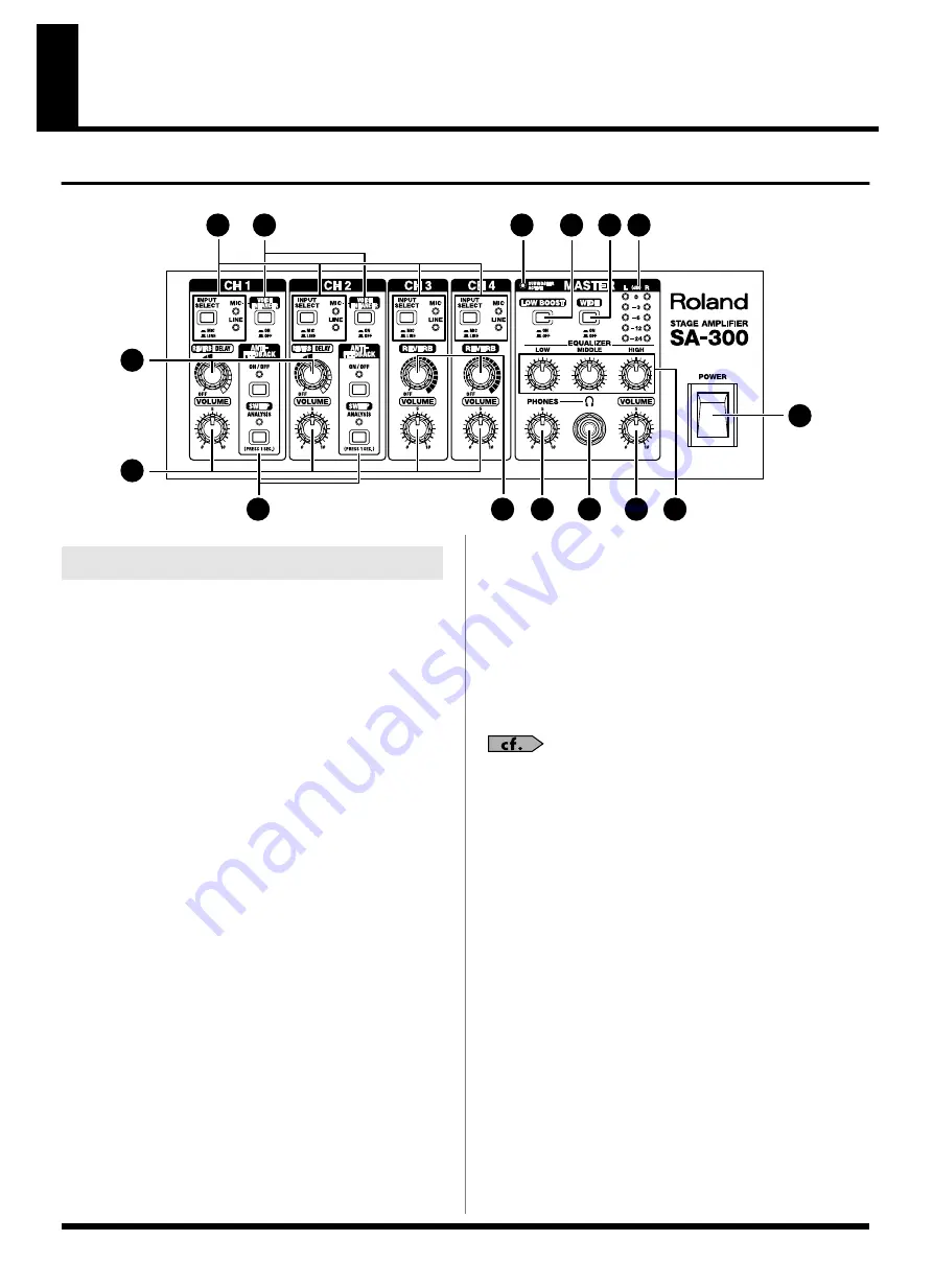
fig.01-01


1. INPUT SELECT Button


Use this button to select MIC or LINE input.

This switches the input to match the connected device 
(mic or line-level device).

The MIC indicator lights when MIC is selected; when 
LINE is selected, the LINE indicator lights.


2.


VOICE ENHANCER Button (CH 1, CH 2)


This switches the Voice Enhancer effect on and off when 
the input is set to MIC.

Switching this on enables you to give the sound a clearer 
contour and make vocals more prominent.


3. REVERB/DELAY Knob (CH 1, CH 2)


You can switch between reverb and delay by adjusting 
the knob position.

When not using reverb or delay, set the knob to “OFF.”

The reverb and delay position on the scale shown on the 
panel is approximate. Listen to confirm the effect as you 
adjust the amount of effect applied.


4. REVERB Knob (CH 3, CH 4)


This adjusts the amount of reverb.

When not using reverb, set the knob to “OFF.”


5. VOLUME Knobs


These adjust the volume levels of the channels.


* To minimize noise as much as possible, we recommend 

turning the VOLUME knob for any channel not being used to 
0 and setting INPUT SELECT to LINE.


6. ANTI-FEEDBACK (CH 1, CH 2)


This automatically detects and eliminates acoustic 
feedback.


For further instructions on how to use anti-feedback, 
refer to “About the Anti-Feedback Function” (p. 16)


ON/OFF Button


Press this button to turn the function on.

When switched on, the indicator lights, and the system 
automatically works to prevent sudden feedback, as well 
as feedback that occurs during quiet stretches.


SWEEP Button


When the ON/OFF button is set to ON, holding down 
this button for one second or longer generates a 
calibration signal from the speakers. The microphone 
picks up the sound and the SA-300 analyzes the 
characteristics of the microphone and the surroundings.

Based on the results of this analysis, the microphone and 
environmental characteristics are compensated for 
automatically, making it difficult for feedback to crop 
up.

The indicator flashes while this automatic correction is in 
progress. When the process is completed, the indicator 
remains lit, signifying that the feedback prevention 
function is in effect.

1

2

14

7

8

9

3

5

4

10

11

12

13

6

15


Channel Controls (CH 1–4)

Summary of Contents for SA-300

Page 1: ... Specifications 21 Owner s Manual Copyright 2005 ROLAND CORPORATION All rights reserved No part of this publication may be reproduced in any form without the written permission of ROLAND CORPORATION Thank you and congratulations on your choice of the Roland SA 300 Stage Amplifier Additionally in order to feel assured that you have gained a good grasp of every feature provided by your new unit Owne...

Page 2: ...ype plug has two blades and a third grounding prong The wide blade or the third prong are provided for your safety If the provided plug does not fit into your outlet consult an electrician for replacement of the obsolete outlet WARNING IMPORTANT As the colours of the wires in the mains lead of this apparatus may not correspond with the coloured markings identifying the terminals in your plug proce...

Page 3: ... amplifier and headphones or speakers may be capable of producing sound levels that could cause permanent hearing loss Do not operate for a long period of time at a high volume level or at a level that is uncomfortable If you experience any hearing loss or ringing in the ears you should immediately stop using the unit and consult an audiologist 011 Do not allow any objects e g flammable material c...

Page 4: ...res for the extension cord Excessive loads can cause the insulation on the cord to heat up and eventually melt through 016 Before using the unit in a foreign country consult with your retailer the nearest Roland Service Center or an authorized Roland distributor as listed on the Information sheet 026 Do not put anything that contains water e g flower vases on this unit Also avoid the use of insect...

Page 5: ...on this device must be placed at a distance of no less than 20 cm from any walls 101a The unit should be located so that its location or position does not interfere with its proper venti lation 102a Always grasp only the plug on the power supply cord when plugging into or unplugging from an outlet 103a At regular intervals you should unplug the power plug and clean it by using a dry cloth to wipe ...

Page 6: ...ergent Afterwards be sure to wipe the unit thoroughly with a soft dry cloth 402 Never use benzine thinners alcohol or solvents of any kind to avoid the possibility of discoloration and or deformation Additional Precautions 553 Use a reasonable amount of care when using the unit s buttons sliders or other controls and when using its jacks and connectors Rough handling can lead to malfunctions 556 W...

Page 7: ...tionally use of Class D power amps for high energy conversion efficiency and switching power supplies reduces generation of unnecessary heat thus permitting use of smaller lighter power transformers and heat sinks Plus the cabinet separates into compact upper and lower units for easy carrying Newly Developed Anti Feedback Function Pre Detection Conventional monitor amps have always presented the r...

Page 8: ...uch as possible we recommend turning the VOLUME knob for any channel not being used to 0 and setting INPUT SELECT to LINE 6 ANTI FEEDBACK CH 1 CH 2 This automatically detects and eliminates acoustic feedback For further instructions on how to use anti feedback refer to About the Anti Feedback Function p 16 ON OFF Button Press this button to turn the function on When switched on the indicator light...

Page 9: ...e 11 PHONES Knob This adjusts the headphone volume level 12 Headphone Jack Connect headphones here Be sure to turn the PHONES knob setting to 0 before connecting or disconnecting headphones The sound from the SA 300 s speakers is not muted when headphones are connected 13 VOLUME Knob This adjusts the overall volume output from the SA 300 s speakers 14 SUBWOOFER ACTIVE Indicator This lights when th...

Page 10: ...uch equipment to malfunction Always be sure to turn the switch off before connecting To protect the circuitry the channel output is muted momentarily after the PHANTOM switch is turned on or off Phantom power is supplied only when a microphone is connected to the XLR connector in the Channel 3 and or Channel 4 MIC jack section Do not connect or disconnect connectors while the phantom power is turn...

Page 11: ...ectly REMOTE SW Using a connection cable to connect foot switches optional BOSS FS 5L and FS 5U you can then use the FS 5L latch type switch to switch the mute on and off and use the FS 5U momentary type switch to turn on and off the effects reverb or delay Mute On Off When the FS 5L s indicator is lit the mute function is switched on and the output from the speakers and headphones as well as from...

Page 12: ...on connecting with Stereo Link refer to About Stereo Link p 15 8 LINE OUT Connectors Jacks Mixers recording equipment and other such devices are connected here Nominal output level is 4 dBu This section includes balanced output compatible XLR type connectors left and right stereo output and 1 4 inch phone jacks stereo output You can use the XLR type connectors and the 1 4 inch phone jacks simultan...

Page 13: ...c optional By connecting any other expression pedals you risk causing malfunction and or damage to the unit When connection cables with resistors are used the volume level of equipment connected to the inputs may be low If this happens use connection cables that do not contain resistors such as those from the Roland PCS series Expression Pedal Roland EV 5 etc Foot Switches White Red Mixer CD Playe...

Page 14: ... from sudden big sound always make sure to have the volume level turned down before switching on power Even with the volume all the way down you may still hear some sound when the power is switched on but this is normal and does not indicate a malfunction About Setting the Volume To obtain the best sound from the SA 300 set the volume level using the following procedure fig 02 04 1 Use the INPUT S...

Page 15: ...angement lets you play in stereo making maximum use of the two SA 300s mixer functions with eight inputs All Channel 4 LINE jacks function as mono inputs fig 02 07 Operation 1 Connect the devices to the SA 300 L and SA 300 R 2 Connect the STEREO LINK OUT R jack on the SA 300 L and the STEREO LINK IN jack on the SA 300 R 3 Connect the STEREO LINK OUT L jack on the SA 300 R and the STEREO LINK IN ja...

Page 16: ... to achieve an acoustically stable system that automatically controls the occurrence of feedback and makes it more difficult for feedback to arise Dynamic Function 1 Suppresses feedback that occurs at times when there is no sound from the microphone For feedback generated when no audio is being input via the microphone for example at times when the performer is not at the microphone the feedback p...

Page 17: ...evel and directed at the SA 300 3 Hold down the ANTI FEEDBACK SWEEP button for at least one second The indicator flashes and the sound of the calibration signal is output from the speaker The calibration signal is set automatically in accordance with the position of the mic and the volume setting Take care not to stand between or leave any object obstructing the space between the mic and the SA 30...

Page 18: ...fiers fig 03 02 When stacking be sure to follow the instructions below Be sure to set up and use these units in stable level locations Be careful not to get your fingers pinched OK NG About the Protection Circuit This unit is equipped with a protection circuit The protection circuit helps ensure safety by activating when excessive input continues for a long time while the device is at a location w...

Page 19: ...40 cm 55 1 8 or a leg spread of less than 120 cm 47 1 4 may result in damage to equipment or injury due to the stand tipping over When using SA 300 with a speaker stand the speaker stand must be carefully placed so it is level and sure to remain stable Cables connected to SA 300 should be given enough slack to prevent accidents that might result from someone tripping over them To prevent accidents...

Page 20: ...Y REVERB REVERB LINE R LINE L MONO MIC CH1 CH2 CH3 CH4 STEREO LINK MIC LINE L MONO MIC LINE L MONO LINE R LINE L MONO MIC IN LINE R LINE L LINE R LINE R LINE L LINE R SPEAKER SA 300W R L PHONES L R L MONO R OUT L OUT R VOLUME INPUT SELECT MIC LINE CH1 VOLUME CH2 VOLUME MASTER VOLUME PHONES VOLUME CH3 VOLUME CH4 VOLUME INPUT SELECT MIC LINE INPUT SELECT MIC LINE INPUT SELECT MIC LINE REVERB LINE OU...

Page 21: ...S VOLUME Knob POWER Switch GND LIFT Switch Indicators MIC LINE CH 1 CH 4 ANTI FEEDBACK ON OFF CH 1 CH 2 ANTI FEEDBACK SWEEP CH 1 CH 2 LEVEL METER SUBWOOFER ACTIVE Connectors CH 1 CH 2 MIC INPUT Jacks XLR type 1 4 TRS phone type LINE INPUT Jacks L MONO R 1 4 phone type CH 3 CH 4 MIC INPUT Jacks XLR type 1 4 TRS phone type PHANTOM Power LINE INPUT Jacks L MONO R 1 4 phone type LINE INPUT Jacks L R R...

Page 22: ... 8 H inches Weight 10 5 kg 23 lbs 3 oz Accessories Owner s Manual Speaker connection cable Options Foot Switch FS 5L Mute BOSS FS 5U ANTI FEEDBACK Effect BOSS FS 6 BOSS Expression Pedal EV 5 FV 300L BOSS FV 500L BOSS FV 500H BOSS Connection Cable PCS 31 In the interest of product improvement the specifications and or appearance of this unit are subject to change without prior notice ...

Page 23: ...o communications However there is no guarantee that interference will not occur in a particular installation If this equipment does cause harmful interference to radio or television reception which can be determined by turning the equipment off and on the user is encouraged to try to correct the interference by one or more of the following measures Reorient or relocate the receiving antenna Increa...

Page 24: ...SD000706 1 DH ...

Reviews: