background image

41

2. Creating 3D Data

2-5 Saving and Exporting Data

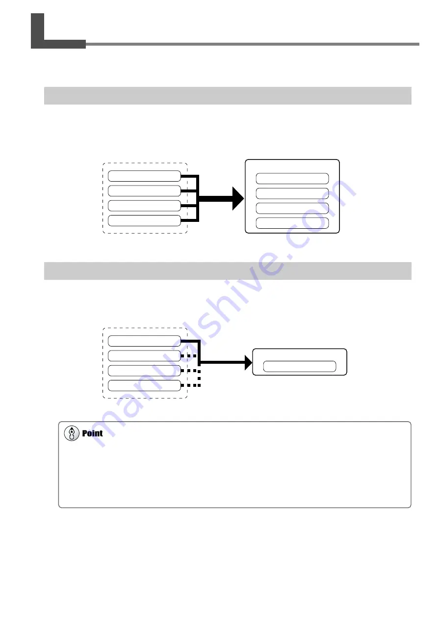
You can take data obtained by scanning and creating polygon meshes and save it in a file format compatible with Dr.
PICZA3. You can also convert (export) data and save it in a file format allowing import into other programs.

Saving Data

Go to the [File] menu and click [Save As]. The data is saved in Dr. PICZA project format (with the file extension .pij).
In addition to working with saved files with Dr. PICZA3, you can edit them using 3D Editor, an editing program for 3D
data.

About Exportable Data

Scanning data is data for measuring points (scanning points) obtained by scanning.
Polygon-mesh data is data composed of new polygons created by estimating the proper shape of the scan object from the
scanning data.
Line-scan data and point scan data are measuring-point data newly obtained respectively by line scanning and point scanning.
However, the exportable file formats for each type of data are predetermined.
For detailed information, refer to the online help for Dr. PICZA3.

Exporting Data

When you want to take data obtained by scanning and make use it with a 3D CAD program or other such program, you
export the data.

Scanning data

Polygon-mesh data

Line-scan data

Point-scan data

Dr.PICZA project format

Scanning data

Polygon-mesh data

Line-scan data

Point-scan data

Save

All data is saved in a single file.

Scanning data

DXF format, STL format etc.

Scanning data

Polygon-mesh data

Line-scan data

Point-scan data

Export

Choose some data.

Summary of Contents for Picza LPX-1200

Page 1: ...anual and the specifications of this product are subject to change without notice The operation manual and the product have been prepared and tested as much as possible If you find any mis print or er...

Page 2: ...anada CLASS A NOTICE This Class A digital apparatus meets all requirements of the Canadian Interference Causing Equipment Regulations CLASSE A AVIS Cet appareil num rique de la classe A respecte toute...

Page 3: ...burning odor un usual noise or the like Doing so may result in fire or electrocution Immediately unplug the power cord plug from the electrical outlet and contact your authorized Roland DG Corp deale...

Page 4: ...topple over The table rotates during scanning Tipover or contact by the scan object may cause dam age Scan object damage is not covered by warranty Do not use with a damaged AC adapter power cord or...

Page 5: ...e Labels Affixed to the AC Adaptor and Unit Front AC Adaptor In addition to these symbols the symbol shown below is also used Indicates a handy tip or advice regarding use Rating label Use a rated pow...

Page 6: ...ing use Failure to do so may make scanning impossible Use a shielded USB cable having a length of three meters or less Never use a USB hub or the like Failure to do so may make scanning impossible Imp...

Page 7: ...cting the Power Cable 15 1 3 Installing and Setting Up the Software 16 Installing the Driver 16 What to Do If Installation Is Impossible 22 Installing the Programs 24 Making the Settings for Using Dr...

Page 8: ...2 When Moving the Machine 53 5 Appendix 55 5 1 Specifications 56 Machine Specifications 56 System Requirements for the Software 56 System Requirements for USB Connection 56 5 2 Table Dimensional Draw...

Page 9: ...two modes you can even scan objects with complex shapes A Wide Array of Scanning Functions In addition to the two basic scanning modes line segment and point scanning functions are also supported By u...

Page 10: ...this documentation on your computer screen Installing the program enables you to view the documentation See 1 3 Installing and Setting Up the Software It provides detailed descriptions of the command...

Page 11: ...safety devices Never insert any objects here Doing so may keep the door open and prevent the safety de vices from working properly Power button This switches the power on and off To switch on the powe...

Page 12: ...n error has occurred Lit or flashing red See 4 1 What to do if Illumination pattern blue and red Dark The status of the LPX 1200 Status Indicated by the Movement Lights These light up blue and move cl...

Page 13: ...11 1 Preparing the Machine This section describes what to do when you first open the packing in cluding how to connect the machine to a computer and install the pro grams and the like...

Page 14: ...the Machine 1 1 Checking Accessaries The following items are packed with the machine Make sure they are all present and accounted for AC adaptor 1 Clay 1 CD ROM 1 User s Manual 1 Roland LPX EZ Studio...

Page 15: ...13 1 Preparing the Machine 1 2 Installing Installation Environment Place in a level stable location...

Page 16: ...ad retainer and the screws The head retainer and packing will be needed if you must repackage the product Please do not throw them away See 4 2 When Moving the Machine 1 2 Installing Packing Packing P...

Page 17: ...he power cord and the AC adapter 1 2 Installing The rear of the machine When you connect the power cable to the machine the power button and movement lights flash momentarily but this is normal and do...

Page 18: ...on Is Impossible Procedure Windows XP 1 Start Windows and log on as Administrator 2 Insert the Roland Software Package CD ROM into the CD ROM drive The setup menu appears automatically 3 Switch on the...

Page 19: ...ith installation and setup 6 Select Install the software automatically then click Next 7 When this dialog box appears click Continue Anyway Installation starts automatically 8 Click Finish The Welcome...

Page 20: ...continues for about one minute From this point on keep the machine s door closed until installation ends Failure to do so switches off the power which may prevent installation from com pleting correct...

Page 21: ...elect the CD ROM drives check box then click Next 8 Click Next Installation starts automatically 9 Click Finish The Welcome to the Found New Hardware Wizard dia log appears 10 Carry out steps 5 throug...

Page 22: ...about one minute From this point on keep the machine s door closed until installation ends Failure to do so switches off the power which may prevent installation from com pleting correctly 4 Connect...

Page 23: ...nd Software Package CD ROM to search the driver 8 Execute installation of the driver 9 Click Finish Installation is executed automatically This completes the installation of the driver 1 Choose Specif...

Page 24: ...Windows 2000 Me 98 From the Start menu choose Settings then Control Panel then click Add Remove Programs 3 Uninstall Roland LPX 1200 USB Device 4 Detach the USB cable connected to the printer 5 Restar...

Page 25: ...lete LPX 1200 Windows XP 2000 Windows Me 98 4 Close the Device Manager dialog and click OK 5 Follow steps 4 through 6 on the previous page to redo installation from the beginning 1 Double click this 2...

Page 26: ...machine 1 Make sure the screen shown in the figure is displayed 2 Follow the on screen instructions to start instal lation and setup 3 When the screen shown in the figure appears click Next Thereafter...

Page 27: ...Roland Dr PICZA3 then Dr PICZA3 2 Go to the File menu and click Preferences 3 Make the setting for the communication port and the unit of measurement to use with Dr PICZA3 This completes all the prepa...

Page 28: ...26...

Page 29: ...27 2 Creating 3D Data This chapter describes how to create 3D data using the machine and the included Dr PICZA3 program...

Page 30: ...the scan object is suitable for scanning and if so mount it on the machine See 2 2 Mounting the Scan Object 2 Perform scanning Use Dr PICZA3 to carry out scanning basic scanning See 2 3 Performing Sc...

Page 31: ...to be scanned is one that can be scanned on this machine Object size An object that protrudes beyond the table or whose height is too high cannot be scanned In such cases consider separating the obje...

Page 32: ...and highly reflec tive objects metals mirrors etc Yes No Object material An object that has a comparatively smooth surface is suitable for scanning Fabrics and objects that have a rough nap cannot be...

Page 33: ...the reflection of the laser beam allowing the object to be scanned The surfaces that reflect laser light as the table rotates and the ob ject passes through this area can be scanned When scanning an...

Page 34: ...appears 3 Choose the scanning mode that matches the shape of the scan object The Settings for Scanning dialog box appears Object whose shape is close to a sphere or cylinder Object with little uneven...

Page 35: ...review to Top View 6 When scanning ends the results of scanning appear Go to 2 3 Performing Scanning and see Checking the Scanning Results Setting screen for scanning plane scan This sets the number o...

Page 36: ...lt in extremely slow processing by the computer We recommend making sure enough memory is in stalled in the computer when you are performing scans that use up large amounts of memory For reference Max...

Page 37: ...ins a number of objects This indicates the name of the object This switches between showing and hiding the group and the object Checking the Scanning Results You can examine the results of scanning wh...

Page 38: ...ompletion of the 3D data Perform coarse scanning of the entire object Rescan required areas in detail Even when holes are present Line Scan Point Scan You use line scanning and point scanning when you...

Page 39: ...ne scanning pitch It may be a good idea to perform rescanning in the same mode you used for the basic scanning When you want to perform fine detail scanning of the surface pattern of a scan object who...

Page 40: ...ea You can specify more than one rescanning area SPACE key drag left or right to shift the perspective Shortcut Keys for Shifting the Perspective To Rotate the Object Hold down the SPACE key and drag...

Page 41: ...want to respecify the rescanning area click the object at any location to release the area already speci fied Setting the Scanning Pitch When performing rescanning make the setting for the scanning pi...

Page 42: ...parameters and create it again Tips for Creating a Polygon Mesh To create a polygon mesh having a high degree of completion you may need to scan at as fine a pitch as possible in order to increase th...

Page 43: ...s data composed of new polygons created by estimating the proper shape of the scan object from the scanning data Line scan data and point scan data are measuring point data newly obtained respectively...

Page 44: ...file format you want to use for exporting 3 Depending on the file format you clicked a dia log box may appear Choose a selection sup ported by the program with which you want to share the data then c...

Page 45: ...43 3 Editing Scanning Results Using 3D Editor This chapter describes the basic methods of operation for 3D Editor the 3D data editing program included with the machine...

Page 46: ...t surfaces is also possible Delete You can delete unneeded objects Merge You can unite a number of objects There is even an alignment feature for doing this Reduce the number This reduces the amount o...

Page 47: ...port button to import more than one set of data and place a number of objects in the 3D Editor window 3 2 Importing and Exporting Data This section describes how to import and export data using 3D Edi...

Page 48: ...seen from directly in front You use it at times such as when you want to move only in the X or Z direction Y direction movement is not possible Top This is a view of the object seen from directly abo...

Page 49: ...n at the point where you have scanned an apple using Dr PICZA3 Procedure 1 Start 3D Editor 2 Try cutting the apple vertically First do the preparation 3 3 Basic Operations for Objects Click the Run 3D...

Page 50: ...3 3 Basic Operations for Objects 1 Click the Select Object button 2 Click the left part of the apple to select it 3 Click the Move Object button 4 Drag the portion you selected to the left The apple...

Page 51: ...carried out from any perspective except Side The cut off portion is deleted 1 Click the Select Object button 2 Click the cut off portion to select it 1 Click the Select Object button 2 Click the righ...

Page 52: ...50...

Page 53: ...51 4 What to Do If This section describes how to resolve problems that can occur during operation and what is required when moving the machine to a different location...

Page 54: ...mmunication port is set correctly See 1 3 Installing and Setting Up the Software The message COM not ready appears on the computer Is the machine powered up Be sure to turn on the machine before you r...

Page 55: ...oor is closed then turn on the machine 2 Start LPX Head Move From the Start menu choose All programs or Pro grams then Roland Dr PICZA3 then LPX Head Move 3 When the screen in the figure appears click...

Page 56: ...54...

Page 57: ...55 5 Appendix...

Page 58: ...blished by Roland DG 5 kg Wavelength 645 to 660 nm Maximum output less than 390 W maximum output of the laser light emitted inside housing is 5 mW Noncontact laser sensor Spot beam triangulation Table...

Page 59: ...57 5 Appendix 9 screw holes M6 depth 7 mm 70 130 110 30 4 5 4 5 1 1 scale 5 2 Table Dimensional Drawing Unit mm...

Page 60: ...58...

Page 61: ...59...

Page 62: ...60...

Page 63: ......

Page 64: ...he media on which the backup copy of the Software is recorded does not belong to the Company 4 Forbidden items 1 This copy of the Software or a backup copy of the Software must not be used on multiple...

Reviews: