background image

How to Restore the Factory Settings (System Initialize)

When the SPD-20 is shipped, it contains 99 Patches in memory. You can freely overwrite this data.
However, the same data is also preserved in ROM, and can be restored at any time. This procedure is
called System Initialize.

The explanations in this manual assume that the SPD-20 is still in its factory initialized state. We recom-
mend that before you begin using the unit, you perform this System Initialize operation.

When you execute the System Initialize operation, all your edited data will be lost. If your SPD-20
contains important edited data, you should make a note of the settings or store the data in an external
device such as a sequencer (p. 75).

1

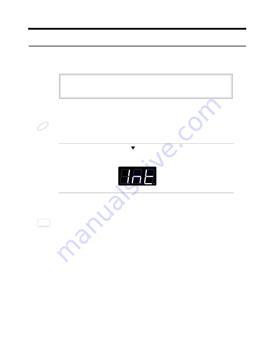
While holding down [

] and [ALL/ENTER], turn the power on.

The following display will appear.

fig.5

2

Press [ALL/ENTER] and the data will be initialized.

If you wish to quit without initializing, press any key other than [ALL/ENTER].


It is possible to restore the factory settings of a single patch with Patch Copy (p. 32).


ROM

This is an abbreviation for Read Only Memory, which is a type of memory that can only be read;
modification or deletion is not possible.

NOTE

MEMO

11

1

2

3

4

5

Summary of Contents for Octapad SPD-20X

Page 1: ... enclosed in square brackets indicate panel buttons or controls For example LAYER signifies the Layer button Items marked by are supplementary explanations Items headed by explain important points concerning the operation of your SPD 20 Items preceded by give you useful tips and information regarding the use of the SPD 20 MEMO NOTE Before using this unit carefully read the sections enti tled USING...

Page 2: ...ed Roland distribu tor as listed on the Information page Never use or store the unit in places that are Subject to temperature extremes e g direct sunlight in an enclosed vehicle near a heating duct on top of heat generating equipment or are Damp e g baths washrooms on wet floors or are Humid or are Dusty or are Subject to high levels of vibration When using the unit with a rack or stand recom men...

Page 3: ...cord Excessive loads can cause the insulation on the cord to heat up and eventually melt through Before using the unit in a foreign country consult with your retailer the nearest Roland Service Center or an authorized Roland distributor as list ed on the Information page The unit and the AC adaptor should be located so their location or position does not interfere with their proper ventilation Alw...

Page 4: ...nimum Level TRIG THRESHOLD 31 Copying a Patch COPY 32 Setting Up Your Own Patch Sequences Patch Chain 33 What is a Patch Chain 33 Setting up a Patch Chain 33 Using a Patch Chain to Select Patches 34 Erasing a Patch Chain 34 CHAPTER 3 Connecting External Pads or Pedals Connecting External Pads or Hi Hat Control Pedal 35 Connecting External Pads or the Special Pedal 35 Precautions When Connecting a ...

Page 5: ...w a function works use the index to find the appropriate explanation CHAPTER 1 Quick Start Read this chapter first to learn how to play using the SPD 20 It guides you quickly through the basics up to the point where you can produce sound All the fundamental operat ing procedures are also introduced CHAPTER 2 Using the SPD 20 by Itself Read this chapter if you wish to use the SPD 20 as a stand alon...

Page 6: ...owever in certain cases such as when circuitry related to memory itself is out of order we regret that it may not be possible to restore the data and Roland assumes no liability concerning such loss of data Memory Backup This unit contains a battery which powers the unit s memory circuits while the main power is off When this battery becomes weak the message shown below will appear in the display ...

Page 7: ...lay rim shots What s more you can play the SPD 20 s sounds using an acoustic drum trigger attached to an acoustic drum p 45 When a hi hat control pedal FD 7 sold separately is connected you have continuous con trol from closed to open of the hi hat sounds p 54 Settings for the SPD 20 s 8 pads 4 external pads hi hat control pedal and the effects unit can be stored as one of 99 Patches This means th...

Page 8: ...r unit should the plug be pulled out accidentally and to avoid applying undue stress to the AC adaptor jack anchor the power cord using the cord hook as shown in the illustration 2 1 3 5 4 14 13 15 6 7 8 9 10 1112 Pad1 Pad2 Pad3 Pad4 Pad5 Pad6 Pad7 Pad8 16 17 18 19 20 21 22 23 24 25 NOTE Panel Descriptions 8 ...

Page 9: ...t Patches In the Edit mode they are used to modify parameter values p 14 16 VOLUME knob Adjusts the volume of the OUTPUT jacks and PHONES jack p 13 17 PHONES jack A pair of stereo headphones can be connected to this jack Even with headphones connected the OUTPUT jacks will still be active p 12 18 OUTPUT R L MONO jacks These jacks output the sound of the SPD 20 For monaural output use the L MONO ja...

Page 10: ...ved in step 1 to attach the stand hold er to the bottom of the SPD 20 fig 4 The screws included with the APC 33 cannot be used Using the Slit Tape Included Place the Slit tape included with the SPD 20 along the slits or grooves around each of the pads The Slit tape allows you to clearly distinguish where each pad is even on stage or in other darkened loca tions fig Slit Tape Please note that Rolan...

Page 11: ...the System Initialize operation all your edited data will be lost If your SPD 20 contains important edited data you should make a note of the settings or store the data in an external device such as a sequencer p 75 1 While holding down and ALL ENTER turn the power on The following display will appear fig 5 2 Press ALL ENTER and the data will be initialized If you wish to quit without initializing...

Page 12: ...e connections have been completed turn on power to your various devices in the order speci fied By turning on devices in the wrong order you risk causing malfunction and or damage to speak ers and other devices Always make sure to have the volume level turned down before switching on power Even with the volume all the way down you may still hear some sound when the power is switched on but this is...

Page 13: ... Control Pedal p 40 Not set PATCH CHAIN ON OFF Off Functions and parameter settings other than these are retained even when the power is turned off Whenever the unit is to remain unused for an extended period of time disconnect the AC adaptor Adjusting the Volume When you strike a pad it will trigger the sound that has been assigned to it Playing harder will pro duce a louder sound As you play adj...

Page 14: ...ctory patch names are listed on p 93 What is a Patch A Patch contains data determines how each pad sounds settings for the effects and also MIDI settings The SPD 20 can store 99 different Patches fig 11 When you select a Patch the settings for each pad are instantly changed p 15 You can also use MIDI Exclusive messages to store Patch data in an external sequencer or other device p 75 MEMO Pad 2 Ex...

Page 15: ...nce the Patch numbers When using the footswitch as a Hold Pedal please refer to Using a Footwitch as a Hold Pedal on p 41 Comparing Layered Sounds Most of the factory preset Patches use Layer p 17 Select a layered Patch and listen to the sounds of pad banks A and B When you select a layered Patch both PAD BANK indicators A and B will light 1 Select a Patch 2 In the Play mode press LAYER to turn La...

Page 16: ...h Patch contains two pad bank settings A and B fig 13 When you select a Patch the PAD BANK indicator will show which pad bank the Patch uses If the Layer function explained below is used in that Patch both PAD BANK indicators A and B will be lit fig 14 Pad Bank B Pad Bank A Pad 2 4 Rims 4 External Pads Pad 1 Pad 3 Pad 4 Pad 6 Pad 5 Pad 7 Pad 8 16 ...

Page 17: ...se the Layer function By assigning different Instruments to pad banks A and B and setting pad banks A and B to different Velocity Curves p 24 your playing dynamics can be used to cross fade or switch between the two sounds Velocity Mix Playing dynamics will determine the mix of the two sounds fig 15 a Velocity Switch Playing dynamics cause a switch between the two sounds fig 15 b Velocity Crossfad...

Page 18: ...from the SPD 20 as you might enjoy with an acoustic drum kit In addition the SPD 20 is MIDI compatible meaning that it can be connected to any other MIDI compatible device sequencer sampler etc regard less of the manufacturer This allows you to create a very powerful music system Product Overview Self contained compact MIDI pad controller 8 dynamics sensitive pads 700 sounds with 16 bit dynamic ra...

Page 19: ...elay to the sound from the sound generator You can select from 25 effects combinations p 28 Play Mode and Edit Mode The SPD 20 has two modes the Play mode and the Edit mode Press EDIT to switch between them fig 17 Play Mode In this mode you can strike the pads and select Patches In the Play mode the display will show the Patch number Edit Mode In this mode you can make settings for the various par...

Page 20: ...er is being edited i e the intersection of the indicated column and row is the cur rently selected parameter The display shows the value of this parameter To edit a particular parame ter refer to the parameter list and use the SELECT and buttons to select it fig 18 Use PATCH VALUE or to modify the parameter value MEMO Selected Parameter Value flashing The intersection of the indicated column and r...

Page 21: ...ight when you press and the one below the one currently lighted will light when you press fig 19 In this illustration the DECAY parameter in the SOUND parameter group is selected 3 Use PATCH VALUE or to set the value The previous value of the parameter will be discarded In the case of a numerical value PATCH VALUE increases the value and PATCH VALUE decreases it You can speed up the change in valu...

Page 22: ... Sounds E01 E46 Artificial Sound Effects n01 n31 Natural Sounds Human Voice r01 r20 Ambience Reversed Sounds Mut Forces Phrase Loop Instrument to stop MUTE No sound oFF No sound The Hi Hat Cymbals for pedal control instruments H01 H17 can be used effectively only when a Hi Hat controller FD 7 separately sold is used p 54 If the Instrument assign setting for any Pad is set to oFF there will be no s...

Page 23: ... time fig 20 For some Instruments raising the decay beyond a certain point will not be possible When the connected pedal is assigned to HH p 54 the decay parameter has no effect on Hi Hat Cymbals for pedal control instruments H01 H17 Changing the decay setting for a Phrase Loop Instrument p 88 changes the attenuation time at the end of the loop Adjusting the Stereo Position PAN This parameter dete...

Page 24: ...bank B respectively striking the pad lightly sounds the Instrument of pad bank A and the harder you hit the louder you can make the sound of the pad bank B Instrument become Velocity Crossfade Ex 2 In a layered patch when you combine SF3 and Hd3 or SF4 and Hd4 as the Velocity Curve settings for pad bank A and pad bank B respectively you can switch the pad bank A and pad bank B Instruments with the...

Page 25: ...a setting of 0 there will be no effect The overall effects level for a Patch is determined by FX LEVEL in the FX PEDAL parameter group fig 25 This FX SEND parameter will have an audible result only if the FX ON OFF setting is on and FX LEVEL in the FX PEDAL parameter group is set above 0 Pad Bank A Pad Bank B Velocity Crossfade Velocity Switch Hard 1 Soft 1 Hard 3 Soft 3 Pad Bank A Pad Bank B MEMO...

Page 26: ...nd by setting Layer to OFF 5 Press BANK A B to select the bank you wish to edit The selected PAD BANK indicator will be flashing 6 Press SELECT to select the SOUND parameter group fig 26 7 Press or to select the parameter to be edited 8 Use PATCH VALUE or to set the value For a numerical parameter pressing PATCH VALUE will decrease the value and pressing PATCH VALUE will increase the value Pressin...

Page 27: ... parameter value Setting all pads to the same parameter value If you press ALL ENTER after step 8 the displayed parameter value will be set for all pads of the cur rently selected pad bank fig 27 If you are making settings for one of the SPD 20 s pads the settings will be applied to all 8 pads If you are making settings for an external pad the settings will be applied to all 4 of the external pads...

Page 28: ...lations to the sound 18 25 Delay sound Adds an echo like effect For details on each effect type refer to the page 79 The effects are toggled on off with each press of FX ON OFF Setting Effect Duration and Rate FX TIME This sets the duration of reverberation or the modulation rate 1 32 The higher the value the longer the reverb duration or the higher the modulation rate The result will be different...

Page 29: ...t the value 6 Repeat steps 3 5 to finish making the effect settings for the Patch 7 If you wish to adjust the effect depth independently for each pad make the appropriate settings for the FX SEND in the SOUND para meter group for each pad p 25 TXCH NOTE GT TIME PAN CURVE SENS PGMCHG BASICCH BULKDUMP PATCHEXPAND TRIGSENS TRIGTHRESHOLD TRIGTYPE TRIGCURVE INST LEVEL PITCH DECAY PAN CURVE FXSEND FX PE...

Page 30: ...ge the Trigger Sensitivity values This parameter is set for all 8 pads i e the same value applies to all pads However this parameter can be set independently for each connected external pad Trigger Sensitivity TRIG SENS settings are common to all patches 1 Press EDIT to enter the Edit mode 2 Press SELECT to select the SYSTEM parameter group 3 Use or to select TRIG SENS fig 29 4 Strike one of the 8...

Page 31: ...actory Trigger Threshold TRIG THRESHOLD settings for the internal pad reflect the average user s preferences If these settings produce good results for you then there is no need to change the Trigger Sensitivity values This parameter is set for all 8 pads i e the same value applies to all pads However this parameter can be set independently for each connected external pad Trigger Threshold TRIG TH...

Page 32: ...in this patch 2 Press EDIT to enter the Edit mode 3 Press COPY fig 32 4 Use PATCH VALUE or to select the copy source Patch The copy source Patch can be selected from user Patches U1 U99 or factory preset Patches P1 P99 Play the pads to check the selected copy source Patch To quit without copying press COPY 5 Press ALL ENTER and the Patch will be copied fig 32 a 6 Press EDIT once again to return to...

Page 33: ...in 1 In the Edit mode press PATCH CHAIN to select a Chain A b C d e F G H fig 36 2 Use the PATCH VALUE or buttons to select the Patch number 1 99 You can also select Patch numbers using a footswitch connected to the FOOT SW jack 3 Press ALL ENTER 4 Repeat steps 2 3 to create a Chain of Patches Each Chain can consist of up to 16 Patches If you attempt to specify a 17th Patch the display will show F...

Page 34: ...e displayed in the Play mode 2 Each time you press PATCH VALUE or the next Patch in the Chain will be selected After the last Patch in the Chain you will return to the first Patch A footswitch connected to the FOOT SW jack can also be used to select Patches 3 Press PATCH CHAIN several times to return to the Play mode Erasing a Patch Chain Here s how to erase the current Patch Chain settings 1 Pres...

Page 35: ... hat Connecting External Pads or Hi Hat Control Pedal Connecting External Pads or the Special Pedal Example 1 Percussion Set The SPD 20 should be mounted on a stand A commercially available cymbal or tom tom stand works well for this fig 38 Set to TRIG 4 4 Pads PD 7 TRIGGER INPUT 1 3 HH CTRL TRIG 4 CHAPTER 3 Connecting External Pads or Pedals 35 1 2 3 4 5 ...

Page 36: ...witch p 40 to HH CTRL If you wish to connect an external pad set the switch to TRIG 4 fig 39 Set to HH CTRL TRIGGER INPUT 1 3 HH CTRL TRIG 4 TRIG 1 TRIG 2 TRIG 3 HH CTRL TRIG 4 Pad PD 7 Pad PD 120 Kick Trigger Unit KD 7 Kick Pedal Hi Hat Control Pedal FD 7 Roland Tom1 Crash Splash Ride China Tom2 Tom3 Tom4 Kick Snare Hi Hat Hi Hat Control Pedal 36 ...

Page 37: ... only by using Trigger Input jacks 1 and 2 p 38 Precautions when connecting a Kick pedal Kick Trigger Unit When using a kick pedal a specialized Kick Trigger Unit KD 7 sold separately is necessary fig 41 A connecting cable and beater are included with the KD 7 and you may use a favorite bass drum pedal to control the SPD 20 sounds Set the Polarity Switch on the KD 7 to the neg ative position then ...

Page 38: ...120 100 with the TRIGGER parameter TRIG TYPE p 45 With the PD 120 setting the Trigger Type makes it possible for you to play rim shots You can play rim shots with the PD 120 only by using Trigger Input jacks 1 and 2 With the PD 7 and PD 9 you can play rim shots using any of the Trigger Inputs The sound does not change regardless of where you strike the head When using the PD 120 as a snare please ...

Page 39: ...he head portion fig 44 When you play rim shots on the PD 120 with the pad OUTPUT jack facing toward you as shown in the figure strike the rim within the range shown By making rim shots outside this range you will not be able to achieve a reliable rim shot sound rim shots can be played on the PD 120 only through Trigger Input 1 and 2 With the SPD 20 you can choose two separate MIDI sound modules fo...

Page 40: ...recognized by the SPD 20 and will now function correctly fig 47 You may hear a brief sound when you change the position of this switch This is normal and should not be a cause for concern Be very careful not to depress the pedal until the above message is displayed The appropriate settings will be made automatically and the same message will be displayed whenever the power is turned on with the FD...

Page 41: ...cters auto matically move across the display to show a longer message The SPD 20 will sometimes scroll error messages or other helpful information p 87 Hold messages will be transmitted on the channel specified by the Basic Channel There are specific Instruments in the internal sound generator that can also be held with a footswitch p 88 This may not work properly for some MIDI sound modules or so...

Page 42: ... and 2 Press the connected pedal when making the Kick Trigger Unit s tone settings Except for the option of making rim settings MIDI parameter settings for external pads are made the same way as those for internal heads Make settings after referring to MIDI Parameter Settings p 61 It is better not to set and layer two different tones and Velocity Curves using the rim s Pad Bank since the relative ...

Page 43: ...ct the SYSTEM parameter group p 21 2 Use or to select TRIG SENS fig 49 3 Strike the pad or depress the Kick Trigger Unit you wish to edit When you strike the pad the strength with which the pad is struck velocity is shown in the display in six levels Striking the pad hard sets velocity at a value of 127 fig 95 4 Use PATCH VALUE or to set the value About the PD 120 s Rim Sensitivity Available only ...

Page 44: ...uck lightly set the TRIGGER THRESHOLD as low as possible without triggering other connected pads Settings for the internal pads reflect the average user s preferences If these settings produce good results for you there is no need to change these values 1 In the Edit mode select the SYSTEM parameter group p 21 2 Use or to select TRIG THRESHOLD fig 51 3 Strike the pad or depress the Kick Trigger Un...

Page 45: ...Kick Trigger Unit you wish to edit fig 53 Trigger Type rim and head settings are shared for all pads PD 7 9 PD 120 You cannot make settings for the internal pads If you try to select the internal head by striking it is displayed 4 Use PATCH VALUE or to set the value Pad Trigger Types Displayed Description fig 54 For the PD 5 For the PD 7 standard drum pads other manufacturers pads For the PD 9 low...

Page 46: ...ers When you make settings for the Trigger Type a number of internal parameters that do not appear on the panel are set automatically These parameters are known as Advanced TRIGGER parame ters Normally no detailed settings are necessary to match the selected Trigger Type but when you get poor sound even having set the Trigger Type or when using pads or acoustic drum trig gers not covered by a part...

Page 47: ...4 Using PATCH VALUE or set the Trigger Curve 2 1 0 1 or 2 Values correspond to the Trigger Curves shown below 0 denotes the standard Trigger Curve fig 56 To make this setting correctly set the Trigger Sensitivity before setting the Trigger Curve Setting the Same Parameter Values to All Pads When you press ALL ENTER while in Edit mode the parameter values that are set in an external pad are set to ...

Page 48: ... the sensitivity of the PD 120 s rim How to Set Advanced Trigger Parameters The process of making settings for the Advanced Trigger Parameters differs from that when making other settings Special procedures are required to set the parameters in Advanced Edit mode The Advanced Trigger Parameters cannot be found in the Parameter List on the front panel You cannot make Advanced Trigger Parameter sett...

Page 49: ...has been the same as in making normal Trigger Type set tings After setting the Trigger Type the following operation is used to enter Advanced Edit mode 5 Confirm that Trigger Type TRIG TYPE in the SYSTEM parameter group has been selected 6 Hold down EDIT for several seconds This takes you into Advanced Edit mode fig 58 In Advanced Edit mode the SYSTEM Parameter Group indicator flashes One second a...

Page 50: ...Edit mode 10 Then press EDIT once again to return to Play mode ALL ENTER does not function in Advanced Edit mode p 48 Overview of the Process of Making Settings in Advanced Trigger Parameters In Edit mode select and set the TRIG TYPE Press EDIT for about one second Press or to select the parameter to be set When you select the parameter then one second after the name of the parameter is displayed ...

Page 51: ...ng force fig 60 b For reliable detection of Trigger signal output adjust the time for reading the trigger signal Scan Time For more on how to set these values refer to p 48 To maximize the speed at which sounds are triggered set the Scan Time value as low as possible For P 1 and P 2 trigger types increase the Pd7 Scan Time values For K 1 and K 2 increase the Kd7 Scan Time values When you strike th...

Page 52: ...he other false trigger signals that need not trigger a sound Trigger signal attenuation time varies with the type and workings of the connected acoustic drum trigger When using acoustic drum triggers it is recommended that you mute the acoustic drums to suppress excess head vibration For more on how to set these values refer to p 48 Preventing Double Triggering of Kick Pads and Other Instruments M...

Page 53: ...sstalk Cancel value on a pad then when that pad and another pad are struck simultaneously the sound from the pad that is struck more weakly may be omitted To prevent this from occurring set Crosstalk Cancel values as low as possible For more on how to set these values refer to p 48 Setting Rim Sensitivity on the PD 120 Rim Sensitivity riM fig 62 b Available Settings oFF 1 15 You can set the Rim Se...

Page 54: ... d12 d24 Raising and lowering of the pitch p 55 1 In the Edit mode select the FX PEDAL parameter group 2 Use or to select PDL CTRL 3 Use PATCH VALUE or to select the function you wish to con trol You can make settings for each Patch independently Controlling the Opening and Closing of the Hi Hat HH The pedal works as a hi hat control pedal controlling sounds H01 H17 assigned to a pad Stepping on t...

Page 55: ...s d05 down 500 cents a perfect fourth d12 down 1 200 cents one octave d24 down 2 400 cents two octaves Depending on the type of Instrument or on the sound parameter pitch settings there may be a point above which the pitch cannot be raised Adjusting the Volume of the Pedal Hi Hat Sound PDL LEVEL When one of the Hi Hat Cymbals for pedal control H01 H17 sounds is assigned to the pad you can control ...

Page 56: ...the SPD 20 TD 10 TD 7 and TD 5 hi hats with this setting For control of the SPD 11 hi hat set the number to 1 Modulation When recording SPD 20 a performance to a sequencer and playing back the same performance set the Controller Number to 4 Foot This way you can faithfully reproduce the action of the hi hat control pedal 1 In Edit mode select the FX PEDAL parameter group 2 Press or to select PDL C...

Page 57: ...data The SPD 20 conforms to the MIDI spec ification and can be connected to other devices to either control or be controlled How MIDI Data is Sent and Received First we will briefly explain how MIDI data is sent and received MIDI connectors MIDI data is sent and received through the following connectors Use a MIDI cable to connectors these connectors to other devices fig 65 MIDI IN receives data f...

Page 58: ... that is differentiated by channel Channel messages and information that is not differentiated by chan nel System messages Data differentiated by channel Channel messages These messages carry musical performance data Normally these messages do most of the work The result that each type of message produces will depend on the settings of the sound module Note messages These messages notify the sound...

Page 59: ... p 65 When the SPD 20 receives a Program Change message from another MIDI device the Patch will change p 69 Control Change messages These messages convey various types of information that make a musical performance more expressive Each message carries a control number that indicates which function it is to control The result will depend on the MIDI device With the SPD 20 you can transmit PAN Contr...

Page 60: ...variety of devices to exchange information but it is not always true that all types of MIDI messages can be exchanged between all types of devices To help you quickly determine what types of MIDI messages can be exchanged between master and slave the manual of each MIDI device includes a MIDI Implementation chart By looking at this chart you can quickly see what messages the device is able to tran...

Page 61: ... to make any special setting for this just set it to 10 the initial value If you switch Patches while setting Program Changes PGM CHG p 65 the Program Number is sent through the TX CH 1 16 set here When You Are Not Sending MIDI Messages oFF MIDI messages are not transmitted Using the Pads to Control External Devices With these settings Note messages are not transmitted P1 P16 Set this when using t...

Page 62: ...e Name Note Number MEMO Note Pad Note Pad 44 46 42 Sound of an Instrument Hi Hat sound controlled by a Pedal Only the highest note number will be shown About Note Numbers for HI Hats Controlled with Pedals Normally one Instrument will be assigned one Note Number However a hi hat sound H01 H17 controlled by a hi hat control pedal will automatically be given three note numbers the displayed Note Num...

Page 63: ...length of the note Drum sound modules and other sound modules The actual length of time the note sounds will depend on the settings of the MIDI sound module If you are using a pad to play a sound that has a slow attack the note may be too quiet or may be cut off too quickly If so increase the Gate Time Pan PAN If you have connected a MIDI sound module that can receive Pan Control Change messages c...

Page 64: ...locity Sensitivity SENS When striking the pad you can adjust the Velocity Sensitivity 1 15 transmitted to a MIDI device Sensitivity increases as the value is raised allowing you to transmit high Velocity levels even when striking the pad softly If the Velocity Curve parameter has been set to CSt velocity will be transmitted with the following value fig 74 Exponential 1 Exponential 2 Exponential 3 ...

Page 65: ...pad will not be transmitted from the conflicting pad When transmitting Program Numbers set with Program Change PGM CHG by striking the pad set the Transmit Channel TX CH to P 1 P16 p 61 However Note Numbers from a pad set like this are not transmitted so you cannot use them to play an external sound module fig 75 MEMO NOTE 1 1 2 2 3 3 4 4 5 5 6 6 7 7 8 1 2 3 4 5 6 7 8 9 10 11 12 13 14 15 16 17 18 ...

Page 66: ...press while holding If you press ALL ENTER at this point the currently displayed value will be set for all pads If you are making settings for an internal pad this will apply to all 8 internal pads If you are making settings for an external pad this will apply to the 4 external pads and rims You can strike the pad to hear the edited sound If you have layered two sounds it is probably a good idea t...

Page 67: ...e played by incoming note messages of the Note Number specified for each pad Incoming note messages are received on the Basic Channel Setting the Receive Channel Basic Channel The SPD 20 receives MIDI messages note messages Program Change messages Control Change mes sages on its Basic Channel When using an external MIDI device to play the SPD 20 s sound generator set the Transmit Channel of the ex...

Page 68: ...ke such a conflicting setting the dis play will flash more rapidly to inform you that the setting is invalid If the Patch Expand function p 69 is on and more than two same note numbers are included in these five Patches the display will also flash more rapidly Remember that three note numbers are assigned to each Hi Hat Cymbal for pedal control sound H01 H17 If even one of these three note numbers...

Page 69: ... sound module to play drum parts in GM System GS Format and other for mats this is an insufficient number of sounds Therefore the Patch Expand function is provided to make more sounds available for control from an external MIDI device When Patch Expand is turned on the sounds selected for Patches 96 99 will also be available in addition to the currently selected Patch This provides a total of five...

Page 70: ...4 h05 Pop Pedal Hi Hat A03 45 t22 Real Tom 2 A04 46 h04 Pop Open Hi Hat Outer A05 47 t21 Real Tom 1 A06 48 t21 Real Tom 1 A07 49 C01 Crash Cymbal 1 A08 50 t21 Real Tom 1 B01 51 C15 Ride Cymbal 1 B02 52 C06 Chinese Cymbal 2 B03 53 C16 Ride Bell Cymbal 1 B04 54 L27 Tambourine 1 B05 55 C02 Crash Cymbal 2 B06 56 L14 Cowbell 1 B07 57 C02 Crash Cymbal 2 B08 58 L33 Vibra Slap Patch Number 98 pad note ins...

Page 71: ...ng the General MIDI logo can be played back using any General MIDI sound generating unit to produce essentially the same musical performance General MIDI supports the GM Percussion Map in channel 10 GS Format The GS Format is Roland s set of specifications for standardizing the performance of sound generating devices In addition to including support for everything defined by the General MIDI Syste...

Page 72: ... the Sound Generator and the Pad Controller Local Control The Local Control setting allows you to disconnect the pad section from the sound generating section When you wish to record and playback your SPD 20 performances using a MIDI sequencer or comput er set Local Control to off Local Control Off fig 80 L I N E I N L R AC adaptor Audio Equipment Stereo Set Stereo Headphones Computer or Sequencer...

Page 73: ... thru function set the SPD 20 to Local Off It is also useful to set Local Off when using the SPD 20 as a pad controller to play only external sound modules NOTE MEMO MIDI Sequencer Soft Thru On Internal Memory Pad section Sound Generating section Local Control Off MIDI OUT MIDI IN MIDI OUT MIDI IN SPD 20 Trigger Interface section MEMO Soft Thru Soft thru is a function provided in most MIDI sequenc...

Page 74: ...se set SENS p 64 to 8 If you wish to record and playback Patch changes made during a performance you will need to make the following settings as well For only one pad set a Program Number that matches the Patch number p 65 If you wish to record and playback the pedal controller hi hat sound H01 H17 layered with another instrument following setting will be necessary Assign a hi hat cymbal for pedal...

Page 75: ...DI IN of the sequencer 1 Set the ID the same as the Basic Channel s p 67 of the device transmitting the Exclusive Messages 2 Press EDIT to enter the Edit mode 3 Use or to select the BULK DUMP in the SYSTEM parameter group 4 Use PATCH VALUE or to select the Patch data you wish to transmit ALL 1 99 If ALL is selected all Patch data Patch Chain data and system parameter data will be transmitted at on...

Page 76: ...usive data from the other MIDI device When reception begins Lod appears in the SPD 20 s display You are returned to the previous display as soon as the Bulk Load has been completed When Patch data is received the bulk dumped Patch data is written to identical Patch numbers For example if you save Patch Number 21 using bulk dump then when the Patch data is bulk loaded it is stored in Patch Number 2...

Page 77: ...with the Basic Channel the SPD 20 p 67 3 Put the SPD 11 in Edit mode and select the BULK DUMP SYSTEM parameter 4 Select the SPD 11 Patches ALL 1 64 to be forwarded When transmitting data the SPD 11 s Patch Number is written as is to the same Patch Number on the SPD 20 When ALL is selected then Patches 1 64 from the SPD 11 are written to Patches 1 64 on the SPD 20 5 When you press ALL ENTER on the ...

Page 78: ...ed only when the Device ID number of the receiving device matches the Device ID number of the transmitting device In the SPD 20 the Basic Channel number is also used as the Device ID number In some devices the MIDI channel number and the Device ID number can be set independently and will not necessarily be the same When transferring Bulk data to another device refer to the operation manual for tha...

Page 79: ...Tremolo Reverb Tremolo and reverb Reverb Time 11 Chorus A standard chorus Chorus Rate 12 Chorus Room Chorus and room reverb Reverb Time 13 Chorus Hall Chorus and hall reverb Reverb Time 14 Chorus Plate Chorus and plate reverb Reverb Time 15 Flanger A standard flanger Flanger Rate 16 Flanger Reverb Flanger and reverb Reverb Time 17 Flanger Reverb Flanger and reverb Flanger Rate 18 Pitched Delay Rev...

Page 80: ...sition of right center and left Reverb Time This sets the length of the reverberation Chorus Rate This sets the modulation speed of the chorus effect Higher settings result in faster chorusing Flanger Rate This sets the modulation speed of the flanger effect Higher settings result in faster flanging Pitched Delay Pitch This sets the amount of pitch change applied to the delayed sound Higher set ti...

Page 81: ... tings will result in a more tremolo like effect Flanging is often used on metallic sounds such as cymbals or Hi Hats to produce a frequently heard effect Hints on Making Parameter Settings Effects provide many possibilities but if you always use the same heavily applied Reverb or Chorus all the Patches will sound the same It is important to choose effect settings that are appropriate for the song...

Page 82: ... CURVE Velocity Curve in the SOUND parameter group inappropriate Make appropriate settings for the Velocity Curve parameter p 24 No power Power on but unit does not operate Are you using the supplied AC adaptor Other AC adaptors may not work properly If the SPD 20 does not operate even with the correct AC adaptor check whether the correct AC line voltage is being supplied It is best to avoid conne...

Page 83: ...orrect actions caused by the vibration from another pad is processed internally Thus if when two pads are struck at the same time the signal output by one of the pads is extremely weak then that sound is prevented from sounding Being sure to strike both pads in their centers with the same force strength makes it difficult for the sound difficult to be omitted When external pads are connected When ...

Page 84: ...NS in the MIDI parameter group too low Set Velocity Seneitivity to an appropriate value p 64 The volume does not change in response to playing dynamics Is CURVE in the MIDI parameter group set to CSt Set Velocity Curve to an appropriate value p 64 The note duration of the MIDI sound module does not change even though you adjusted GT TIME Does the MIDI sound module recognize Note Off messages Or ha...

Page 85: ...Note Number set correctly The SPD 20 will not produce sound if it receives a Note Number which has not been assigned to a pad Modify the Note Number or select a Patch which has different note numbers assigned to it p 62 Have you assigned the same Note Number to more than one pad Even if you assign the same Note Number to more than one pad only one Instrument will sound Set different note numbers f...

Page 86: ...f the SPD 20 Set the basic channel p 67 Set the SPD 20 s Device ID to the Basic Channel The effect does not work Is FX ON OFF turned off Press FX ON OFF to on p 9 Is the FX LEVEL at 0 Set the FX LEVEL to an appropriate level p 28 Is the FX SEND at 0 Set the FX SEND LEVEL to an appropriate level p 25 The display flashes rapidly during setting of the Note Numbers This indicates that during setting o...

Page 87: ...any but ton will return you to the previous display fig 91 The internal memory data has been lost Press any button on the front panel All data will be initialized and the previous display will reappear If this happens all the data in the SPD 20 will be reset to the factory presets fig 92 This message indicates that there is an irregularity in the voltage of the pad detection circuit Press any butt...

Page 88: ...Rim Shot S10 Steel Snare Soft S11 Steel Snare Hard S12 Steel Snare Rim Shot No Instrument Loop Exc No Hold SPD 11 S13 Loose Snare Soft S14 Loose Snare Hard S15 Loose Snare Rim Shot S16 Medium Snare 1 Soft S17 Medium Snare 1 Hard S18 Medium Snare 1 Rim Shot S19 Medium Snare 2 Soft S20 Medium Snare 2 Hard S21 Medium Snare 2 Rim Shot S22 Concert Snare Soft Exc 1 S23 Concert Snare Hard Exc 1 S24 Conce...

Page 89: ...31 h29 TR 808 Open Hi Hat Outer Exc 31 h30 TR 909 Closed Hi Hat Exc 31 h31 TR 909 Open Hi Hat Exc 31 h32 CR 78 Closed Hi Hat Exc 31 h33 CR 78 Open Hi Hat Exc 31 Hi Hat Cymbal for pedal control No Instrument Loop Exc No Hold SPD 11 H01 Pop Hi Hat Inner Exc 31 H02 Pop Hi Hat Outer Exc 31 H03 Real Hi Hat Inner Exc 31 H04 Real Hi Hat Outer Exc 31 H05 Brush Hi Hat Exc 31 H06 Pure Hi Hat Inner Exc 31 H0...

Page 90: ...1 Tin Exc 14 i09 Tabla 1 Tun Exc 14 i10 Tabla 1 Ti Exc 14 i11 Tabla 2 Te Exc 14 i12 Tabla 2 Na 1 Exc 14 i13 Tabla 2 Na 2 Exc 14 i14 Tabla 2 Tun Exc 14 i15 Pot Drum 1 Low Exc 32 i16 Pot Drum 1 High Exc 32 i17 Pot Drum 1 Accent i18 Pot Drum 2 Mute i19 Pot Drum 2 Long Exc 33 No Instrument Loop Exc No Hold SPD 11 i20 Pot Drum 2 Short Exc 33 i21 Dholak Ga i22 Dholak Ta Exc 34 i23 Dholak Tun Exc 34 i24 ...

Page 91: ...dic Percussion Melodic Instruments No Instrument Loop Exc No Hold SPD 11 M01 Glockenspiel M02 Vibraphone M03 Xylophone M04 Marimba 1 M05 Marimba 2 M06 Bass Marimba M07 Celesta M08 Tubular Bells 1 M09 Tubular Bells 2 No Instrument Loop Exc No Hold SPD 11 Central America M10 Steel Drum 1 M11 Steel Drum 2 India M12 Sitar M13 Sitar Gliss M14 Santoor Upper M15 Santoor Lower M16 Tambura M17 Tambura Dron...

Page 92: ...t 2 E29 Noise Accent 3 E30 Noise Accent 4 E31 Random Noise 1 E32 Random Noise 2 No Instrument Loop Exc No Hold SPD 11 E33 Random Noise 3 E34 Random Noise 4 E35 Slide E36 Uut E37 Drop E38 Emergency E39 Woody 1 E40 Woody 2 E41 Monster Drum E42 Can Drum E43 Wah Guitar Down 1 E44 Wah Guitar Up 1 E45 Wah Guitar Down 2 E46 Wah Guitar Up 2 Natural Sounds Human Voice No Instrument Loop Exc No Hold SPD 11 ...

Page 93: ...ent 48 Japanese Japanese Percussion 49 Korean Korean Percussion 50 Chinese Chinese Percussion No Patch Name Description 51 Yang Qin Chinese Struck Stringed Instrument 52 Southeast Asian Southeast Asian Percussion 53 Gamelan Southeast Asian Percussion 54 Timpani Orchestral Percussion 55 Chimes Bells Orchestral Percussion 56 Orchestra Hits Orchestral Percussion 57 Marimba Melodic Percussion 58 Bass ...

Page 94: ...PAGE 51 52 52 53 53 00 30 1 16 00 64 oFF 30 40 50 60 70 80 oFF 1 15 Lnr EP1 EP4 SP1 SP2 SF1 SF4 Hd1 Hd4 CSt Lnr EP1 EP4 SP1 SP2 SF1 SF4 Hd1 Hd4 CSt 0 15 1 16 oFF P1 P16 S S C S toP 0 127 oFF 01 40 ALt L7 L1 Ctr r1 r7 rnd oFF 1 15 1 128 oFF 1 25 1 32 0 15 HH EFS U07 U12 U24 d05 d12 d24 0 15 oFF 1 4 10 11 16 17 64 1 16 ALL 1 99 oFF on 1 16 0 15 Pd5 Pd7 Pd9 100 120 P1 P2 Kd7 K1 K2 KiK Snr toM FLr 2 1...

Page 95: ...NAME FX PEDAL FX TYPE FX TIME FX LEVEL PDL CTRL PDL LEVEL PDL CC PATCH PARAMETER EXTERNAL PAD MIDI INST LEVEL PITCH DECAY PAN CURVE FX SEND TX CH NOTE GT TIME PAN CURVE SENS PGM CHG HEAD 1 BANK A BANK B RIM 1 BANK A BANK B HEAD 2 BANK A BANK B RIM 2 BANK A BANK B HEAD 3 BANK A BANK B RIM 3 BANK A BANK B HEAD 4 BANK A BANK B RIM 4 BANK A BANK B BASIC TRIGGER PARAMETER ADVANCED TRIG SENS TRIG THRESH...

Page 96: ...ures one way transfer and handshake transfer One way transfer procedure See Section 3 for details This procedure is suited to the transfer of a small amount of data It sends out an Exclusive message completely independent of the receiving device s status Connection Diagram Connection at point 2 is essential for Request data procedures See Section 3 Handshake transfer procedure This device does not...

Page 97: ...h such devices Roland has limited the DT1 to 256 bytes so that an excessively long message is sent out in separate segments A DT1 message is capable of providing only the valid data among those specified by an RQ1 message Some models are subject to limitations in data format used for a single transaction Requested data for example may have a limit in length or must be divided into predetermined ad...

Page 98: ...number 17 Status Second Third BnH 11H vvH n MIDI channel 0H 0FH ch 1 ch 16 vv Parameter Value 00H 7FH 0 127 This transmits the Hi Hat Controller position message as one of the Control Messages set in PDL CC When the Footswitch function is set as a hold pedal then if the pedal is pressed 7FH is transmitted when the pedal is released 00H is transmitted It is transmitted via the MIDI Channel set to t...

Page 99: ...Status Second Third BnH 04H vvH Panpot Controller number 10 Status Second Third BnH 0AH vvH Expression Controller number 11 Status Second Third BnH 0BH vvH General purpose controller 1 Controller number 16 Status Second Third BnH 10H vvH General purpose controller 2 Controller number 17 Status Second Third BnH 11H vvH n MIDI channel 0H 0FH ch 1 ch 16 vv Parameter Value 00H 7FH 0 127 Any one of the...

Page 100: ...rameters 4 1 01 00 00 00 System parameters 4 2 02 00 00 00 Chain setup 4 3 Table 4 1 Patch parameters p Patch No 0 98 t Pad No 1 32 The correspondence of the t value to internal and external pads is as follows 00H 1 BANK A INTERNAL PAD1 07H 8 BANK A INTERNAL PAD8 08H 9 BANK A EXTERNAL HEAD1 0BH 12 BANK A EXTERNAL HEAD4 0CH 13 BANK A EXTERNAL RIM1 0FH 16 BANK A EXTERNAL RIM4 10H 17 BANK B INTERNAL ...

Page 101: ...s Roland System Exclusive messages RQ1 and DT1 have a Checksum at the end of the data before EOX to be able to check for communication errors The Checksum results from address and data or size included in the message How to calculate Checksums H indicates Hexadecimal The error checking process uses a Checksum and provides a bit pattern where the last sig nificant 7 bits are zero when values for an...

Page 102: ...X O 9n v 1 127 X Off 0 127 0 127 X X X O X X X X X X X O X X X X O O O 1 Off 0 127 O X 1 X X X X 1 X X O X 1 16 1 16 Mode 3 X O 9b v 1 127 X Off 0 127 O 0 127 X X O 0 98 O X X X X X X X O X Modulation Foot Pan Expression General Purpose 1 General Purpose 2 Hold 1 Reset all controllers 1 Can be set and stored for each pad 2 Common to Transmitted and Recognized 3 Select one to use as the Hi hat Cont...

Page 103: ...t of each Note On or Note Off message Aftertouch Polyphonic aftertouch is independent for each key in the channel Channel aftertouch applies equally to all keys in the channel Pitch Bend The SPD 20 does not transmit receive this data Control Change These are the Control Change numbers which can be transmitted received and the control functions they can have For details refer to the MIDI Implementa...

Page 104: ... Jack Dual Trigger inputs 1 and 2 accept rim shots from the PD 7 PD 9 and PD 120 while inputs 3 and 4 accept rim shots from the PD 7 and PD 9 Power Supply AC 12 V AC Adaptor Current Draw 420 mA Dimensions 450 W x 350 D x 70 H mm 17 3 4 W x 13 13 16 D x 2 13 16 H inches Weight 2 8 kg 6 lbs 3 oz excepting AC adaptor Accessories Owner s Manual AC Adaptor BOSS BRA Series Slit Tape Options Pads PD 120 ...

Page 105: ...sk Time 52 MIDI 57 MIDI Channels 58 MIDI Implementation 98 MIDI Implementation Chart 102 MIDI Parameter 61 MIDI Connector 57 MIDI Velocity Curve 64 N NOTE 62 Note Number 58 62 Note Off 58 Note On 58 O Open Hi Hat 54 P Pad Bank 16 Pad Section 18 PAN 23 63 Parameter List 20 94 Patch 14 Patch Chain 33 Patch Expand 69 Patch List 93 PD 100 38 45 PD 120 36 37 38 39 45 PD 5 37 45 PD 7 35 36 37 39 45 PD 9...

Page 106: ...xternal pads 47 Set Rim Sensitivity on the PD 120 53 Patch editing Copy Patch settings to another Patch 32 Set all pads to the same parameter value 27 While playing Adjust the overall volume of the SPD 20 13 Get half open sounds with connected FD 7 54 Select Patches 14 Select Patches in a preset order Patch Chain 33 Select Patches using footswitches 15 Select Patches using Program Change messages ...

Page 107: ... plug proceed as follows The wire which is coloured BLUE must be connected to the terminal which is marked with the letter N or coloured BLACK The wire which is coloured BROWN must be connected to the terminal which is marked with the letter L or coloured RED Under no circumstances must either of the above wires be connected to the earth terminal of a three pin plug NEUTRAL LIVE For the U K This p...

Page 108: ...Street ARD E1 Golf Heliopolis Cairo 11341 EGYPT TEL 20 2 417 1828 REUNION Maison FO YAM Marcel 25 Rue Jules Hermann Chaudron BP79 97 491 Ste Clotilde Cedex REUNION ISLAND TEL 0262 218 429 SOUTH AFRICA That Other Music Shop PTY Ltd 11 Melle St Braamfontein Johannesbourg SOUTH AFRICA P O Box 32918 Braamfontein 2017 Johannesbourg SOUTH AFRICA TEL 011 403 4105 Paul Bothner PTY Ltd 17 Werdmuller Centre...

Reviews: