background image


19


Use As a Multi-Viewer

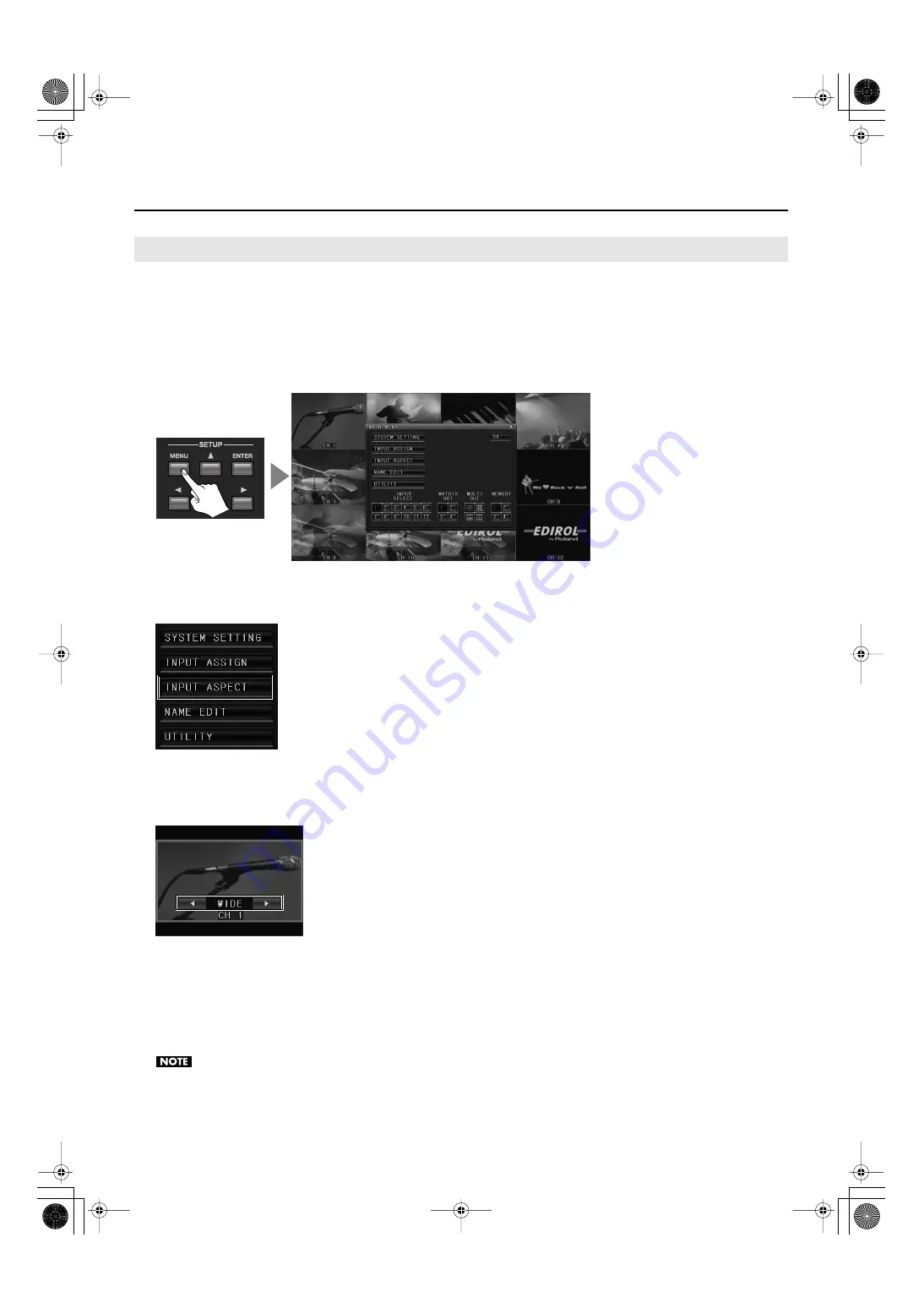
When the input pictures have mixed aspect ratios, you can individually make them letterboxed.


1.


Choose the display pattern.


Use a [MULTI-OUT] button or the mouse to pre-select the display pattern.


2.


Display the menu.


Press the [MENU] button or right-click with the mouse to display the MAIN MENU.


fig.menu-display.eps


3.


Select INPUT ASPECT.


Use the up and down cursor buttons and the [ENTER] button or click with the mouse to choose [INPUT ASPECT].


fig.select-input-aspect.eps


4.


Select a box.


Use the up and down cursor buttons or the mouse to choose a box. The selected box is displayed enclosed in green lines, and the 
current display mode is displayed as shown below.


fig.select-aspect-mode.eps


5.


Change the display mode.


Use the left and right cursor buttons or the mouse to change the display mode.


6.


Quit the menu.


Press the [MENU] button or click the on-screen [OK] button to return to normal screen.


* You can also return to normal screen by right-clicking with the mouse.


Changes in the aspect ratio are enabled only for MULTI-OUT. The setting is not applied to MATRIX OUT.


Changing the Aspect Ratios of the Channels

MVS-12_e.book 19 ページ 2011年3月9日 水曜日 午後2時33分

Summary of Contents for MVS-12

Page 1: ...ned a good grasp of every feature provided by your new unit owner s manual should be read in its entirety The manual should be saved and kept on hand as a convenient reference Copyright 2010 ROLAND CO...

Page 2: ...istribution 3 The name of the author may not be used to endorse or promote products derived from this software without specific prior written permission THIS SOFTWARE IS PROVIDED BY THE AUTHOR AS IS A...

Page 3: ...this manual include illustrations that depict what should typically be shown by the display Note however that your unit may incorporate a newer enhanced version of the system so what you actually see...

Page 4: ...Doing so may cause short circuits faulty operation or other malfunctions 012b Immediately turn the power off remove the AC adaptor from the outlet and request servicing by your retailer the nearest Ro...

Page 5: ...wipe all dust and other accumulations away from its prongs Also disconnect the power plug from the power outlet whenever the unit is to remain unused for an extended period of time Any accumulation o...

Page 6: ...ition Therefore before using the unit you must allow it to stand for several hours until the conden sation has completely evaporated 360 Depending on the material and temperature of the surface on whi...

Page 7: ...os of the Channels 19 Saving Settings to MEMORY Buttons 20 Synchronizing with Operation of the LVS 800 21 Use As a Matrix Switcher 22 Using Buttons to Select the Output Destination and Source 22 Using...

Page 8: ...you may experience a discomforting sensation or perceive that the surface feels gritty to the touch when you touch this device cameras connected to it or the metal portions of other objects such as V...

Page 9: ...ef interval a few seconds after power up is required before the unit will operate normally Turning the Power On Make sure the power cable is securely inserted then press the POWER button located on th...

Page 10: ...a matrix switcher Using these in combination with the MATRIX OUT buttons lets you select the output channel for each source 4 MATRIX OUT Buttons p 22 When you re using the unit as a matrix switcher yo...

Page 11: ...t from the two connectors shown below For information on output format refer to Main Specifications p 37 RGB Connector This is a D Sub 15 pin connector Here you connect a computer monitor or other suc...

Page 12: ...on the MVS 12 When you re using the unit as a matrix switcher make the connections as shown here To prevent malfunction or damage to video cameras or other devices always turn off the power on all dev...

Page 13: ...600HD can be expanded from one to twelve In this case connect cameras and other source devices to VIDEO INPUT 1 through 12 on the MVS 12 Connect MATRIX OUT 1 on the MVS 12 to SD IN channel 13 on the V...

Page 14: ...om MATRIX OUT 1 through 4 fig monitor out eps For information on the output resolution of the MULTI OUT MENU connectors refer to Main Specifications p 37 Connect monitor equipment that is compatible w...

Page 15: ...a mouse be sure to connect it before you switch on the power to the MVS 12 The mouse might fail to operate correctly if connected after powerup fig mouse connection eps You can use the mouse to perfo...

Page 16: ...all channels are displayed You can use the procedure in Changing the Display Location for Channels p 18 to switch displayed channels fig 16x9 monitor out eps If all the MULTI OUT buttons are dark imag...

Page 17: ...e 1 Display the menu Right clicking the mouse displays the MAIN MENU shown below fig selector eps 2 Choose the pattern Click a MULTI OUT button to choose the display pattern fig switch pattern mouse e...

Page 18: ...se a box The selected box is displayed enclosed in green lines and the number of the currently assigned input terminal IN 1 through IN 12 is displayed as shown below fig select position eps 5 Change t...

Page 19: ...t input aspect eps 4 Select a box Use the up and down cursor buttons or the mouse to choose a box The selected box is displayed enclosed in green lines and the current display mode is displayed as sho...

Page 20: ...tion finishes the flashing stops fig panel preset eps 3 Call up the display mode and display locations Pressing the MEMORY button you pressed in step 2 calls up the saved state Displaying the MAIN MEN...

Page 21: ...d the video displayed on the monitor connected to the MVS 12 Preview This is the video selected on the mixer s inactive bus A green box is displayed around the picture Program This is the video curren...

Page 22: ...nel of the source you want to assign to the output destination you selected in step 1 fig select source eps 3 Verify the assignment When you have finished assigning sources press the same MATRIX OUT b...

Page 23: ...destination Use MATRIX OUT buttons 1 through 4 to select the output destination fig matrix mode eps 3 Assign the source Use the INPUT SELECT buttons to choose the channel of the source fig drag sourc...

Page 24: ...the MEMORY button you pressed in step 2 calls up the saved state Displaying the MAIN MENU lets you use the mouse to call up saved values Click any of the MEMORY buttons from 1 to 4 to call up the save...

Page 25: ...ct MIDI output from the V 1600HD to the MIDI IN connector on the MVS 12 Set the MIDI channels and device IDs to matching values and set the MVS 12 to receive MIDI signals from the V 1600HD fig MIDI co...

Page 26: ...ration press the ENTER button to enter into a level below If you re using the mouse to perform this operation you can enter into a level below simply by selecting an item fig push enter eps 4 Change t...

Page 27: ...ches between NTSC and PAL This sets the resolution of output The setting is made automatically by AUTO 1 This sets the aspect ratio of output The setting is made automatically by AUTO This stretches o...

Page 28: ...1 through CH 12 and 1 through 4 to names that you choose Refer to Changing the Names of Channels p 31 fig name edit menu eps UTILITY Menu Selecting this menu item lets you display the Utility menu Fo...

Page 29: ...ig NTSC boot eps Switching to PAL at Startup At MATRIX OUT hold down 2 and turn on the power This button flashes when the unit is switched to PAL at startup Once set to PAL the setting persists in mem...

Page 30: ...witches the output format Pressing the MENU button or clicking the on screen CANCEL button quits the screen and returns to the original output format The output format returns to previous automaticcal...

Page 31: ...e output from PREVIEW jack are changed to capital letters automatically fig name change eps 1 Select the memory number Pre select the memory number for which you want to save a changed name You can sa...

Page 32: ...to enter the name You can use alphanumeric characters for the name To switch between capital letters and small letters use the CAPS button Switching CAPS on or off also switches between numerals and...

Page 33: ...rom The number displayed with SRC to its right is the copy source fig copy source eps 4 Select the number of the copy destination Choose the number of the memory to copy to The number displayed with D...

Page 34: ...he reset operation Clicking the RESET button displays a confirmation prompt Use OK to execute the reset operation Use CANCEL to go back to the original screen fig execute reset eps 5 Quit the menu Pre...

Page 35: ...as a multi viewer remains unrestricted You can display all source video on the monitor connected to the MULTI OUT MENU connector 1 Display the menu Press the MENU button or right click with the mouse...

Page 36: ...hoose UTILITY 3 Execute the factory reset Going to the FACTORY RESET item and clicking the RESET button displays a confirmation prompt Selecting OK executes the factory reset Selecting CANCEL returns...

Page 37: ...or pinched between the rack mount bracket and the rack Remove rubberf feet from bottom panel when you rack mount this unit fig dimension eps Main Specification About Rack Mounting Dimensions Video Pr...

Page 38: ...NU causes the setting values not to be saved Channel numbers are not displayed At the SYSTEM SETTING menu is CH OVERLAY set to OFF Set this to ON for display or to OFF to hide The display is not at th...

Page 39: ...For China MVS 12_e book 39...

Page 40: ...5 1 0 0 0 1 6 8 5 2 0 4 MVS 12_e book 40...

Reviews: