19
6
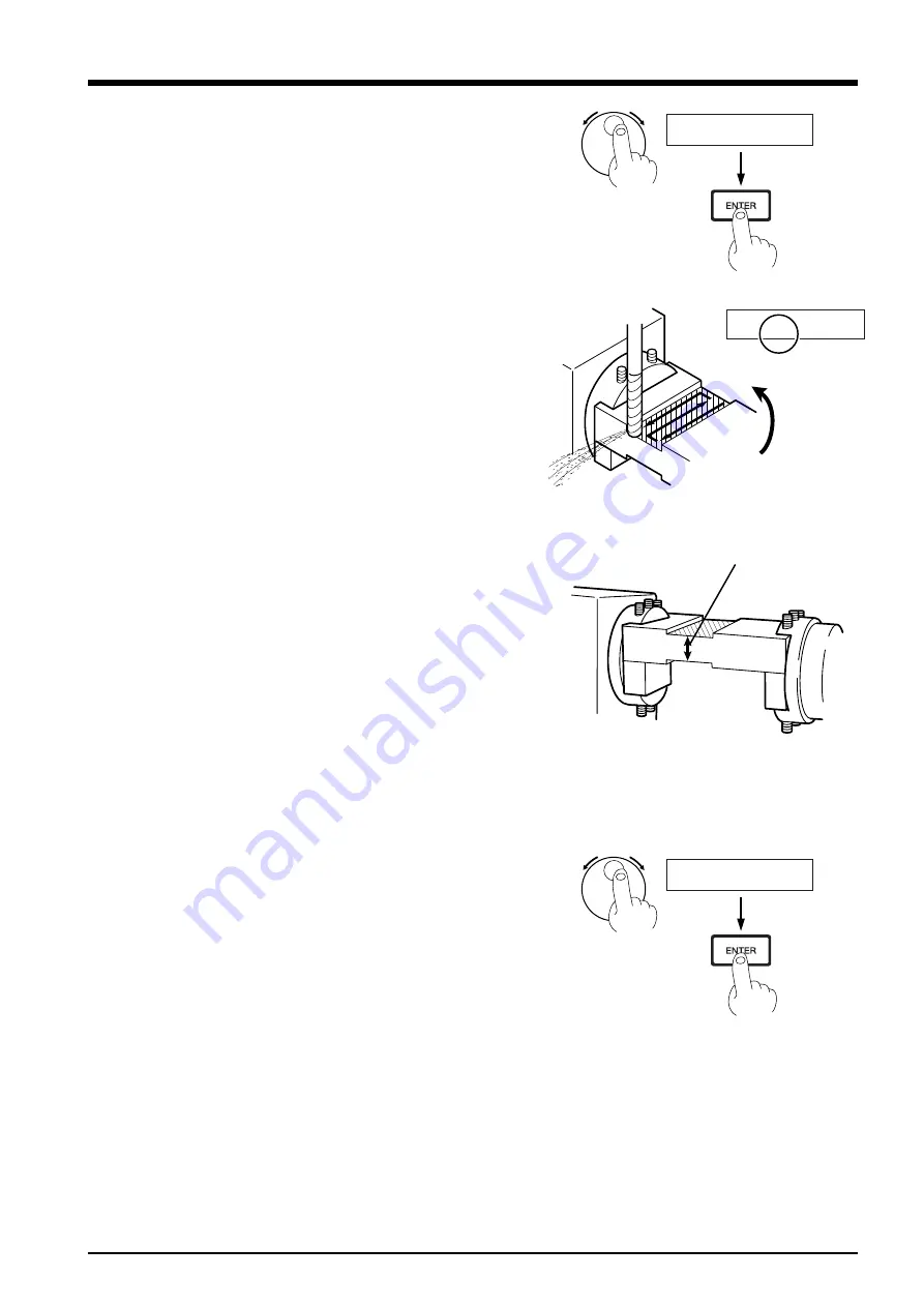
Press the [EXIT] key. Use the dial to select [12 ROTARY CON-
TROL], then press the [ENTER] key. In the same way, go to the
[12-1 ROTATE] menu, then use the dial to make the setting for
[180 deg]. Press the [ENTER] key. The tool rises and the workpiece
is flipped.
Use the [EXIT] key to go back to the coordinate-value screen.
7
Follow steps 3 to 5 to cut the back surface of the workpiece in the
same way. Make a note of the Z-axis coordinate value at this time.
(Label this "coordinate b.")
When you have finished, use the [+Z] key to raise the tool, then
press the [SPINDLE] key to stop the spindle.
8
Use the coordinates a and b that you noted in steps 4 and 7 to
calculate the theoretical value for the finished thickness. Also, use
Vernier calipers or the like to measure the actual thickness of the
cut workpiece. The difference between the theoretical value and
the actual measured value is the amount of error. As a general
guide, the offset value should be one-half of this.
Theoretical thickness = coordinate a + coordinate b
Offset value = (theoretical thickness - actual measured value) / 2
For example, if coordinate a is -80 and coordinate b is 2,250, the
theoretical thickness is 21.7 mm. If the actual measured value is
21.8 mm, the estimated offset value is -50
µ
m.
9
Press the [EXIT] key. Use the dial to select [12 ROTARY CON-
TROL], then press the [ENTER] key. In the same way, go to the
[12-6 CENTER-Z OFFSET] menu and use the dial to set the off-
set value. Press the [ENTER] key.
10
Repeat steps 3 through 9 as required to fine-tune the offset value.
If the actual measured value is larger:
Make the offset value smaller (more of a negative value).
If the actual measured value is the smaller of the two:
Make the offset value larger (more of a positive value).
12-1 ROTATE
180 deg
Part 5 Offset Adjustment for the Y-axis and Z-axis Origin Points
X 4520 Y -3125
*Z 2250 ---------
12-6 CENTER-Z OFFSET
< -50 um>
Actual measured value


