Roland Metaza MPX-60 User Manual Download Page 65

63

5  Troubleshooting

7

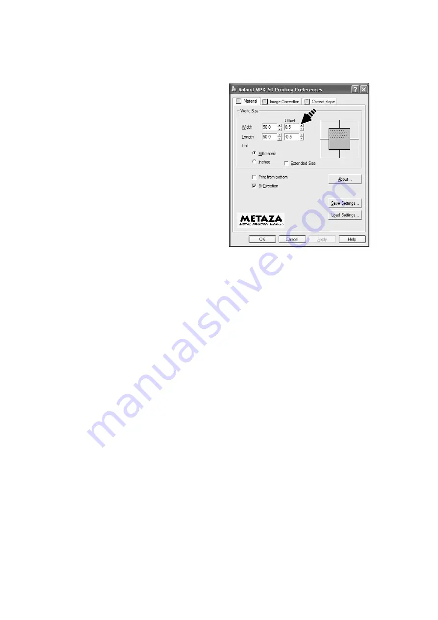
Click the [Material] tab.

8

Enter the dimensions of the displacement you noted in
step 5 as the [Offset] width and length.

Important!

When you open the properties for a driver from a program such as Dr.METAZA2, any values you set are temporary, and are not
saved.
To save the settings for driver properties, go into the [Printers] folder and open the properties for the desired driver.

Summary of Contents for Metaza MPX-60

Page 1: ...ns of this product are subject to change without notice The operation manual and the product have been prepared and tested as much as possible If you find any misprint or error please inform us Roland...

Page 2: ...cial environment This equipment generates uses and can radiate radio frequency energy and if not installed and used in accordance with the instruction manual may cause harmful interference to radio co...

Page 3: ...What to Do If Installation Is Impossible 17 Uninstalling the Driver 19 Windows XP 2000 19 Windows 98 Me 21 2 Performing Marking 22 2 1 Getting Ready to Perform Marking 22 Preparing the Workpiece for...

Page 4: ...Cropping Only Needed Images 43 3 4 Creating a Decorative Frame Around an Image 45 3 5 Registering a Frequently Used Image Symbol 47 3 6 Importing an Image from a Scanner 48 3 7 Adding a Hand drawn Ima...

Page 5: ...at must be carried out The specific thing that must be done is indicated by the design contained within the circle The symbol at left means the power cord plug must be unplugged from the outlet Do not...

Page 6: ...h a damaged AC adapter power cord or power cord plug or with a loose electrical outlet Doing so may lead to fire electrical shock or electrocution When not in use for several hours unplug the power co...

Page 7: ...hese messages Rating label Do not use with any electrical power supply that does not meet the ratings displayed on the AC adapter Indicates information to prevent machine breakdown or malfunction and...

Page 8: ...s is exactly analogous to the way a monochrome printer expresses light and dark area by varying the size and arrangement of dots Printer METAZA If the marking force is not varied according to the hard...

Page 9: ...cure it in place without using commercially available adhesive tape STANDBY LED This lights up when the power is on When it is flashing it indicates that an error has occurred STANDBY key This switche...

Page 10: ...Marking The following items are packed together with the unit Check the following to make sure that you received all the items that were shipped along with the unit AC adapter Power cord CD ROM User s...

Page 11: ...f the following types of areas Avoid use in areas subject to strong electric noise Avoid use in areas subject to high humidity or dust This machine generates heat when used and should not be installed...

Page 12: ...hine remove the protective media Connecting the AC Adapter and Power Cord 1 2 3 NOTICE Do not connect the USB cable yet You connect the USB cable when you install and set up the software See 1 3 Insta...

Page 13: ...8 Me 2000 XP at the time of purchase This includes such computers later upgraded to Windows Me 2000 XP 2 Computers on which USB operation is assured by the manufacturer of computers The ability to mak...

Page 14: ...ow 3 Click Dr METAZA2 Install The Setup program starts 4 Follow the messages to carry out setup and finish setting up the program 1 Switch on the computer and start Windows If you are installing under...

Page 15: ...dows XP NOTICE Keep the machine and the computer unconnected until you carry out this installation operation Failure to follow the correct procedure may make installation impossible See Installing the...

Page 16: ...rking 5 Choose Install the software automatically Recom mended then click Next Installation of the USB driver starts automatically 6 When the screen appears click Continue Anyway 7 Click Finish This c...

Page 17: ...tion impossible See Installing the Driver What to Do If Installation Is Impossible 1 Before you start installation and setup make sure the USB cable is not connected 4 Select Install From Port box sel...

Page 18: ...8 Press the STANDBY key to switch on the machine 7 Remove the CD ROM from the CD ROM drive 9 Connect the machine to your computer using a USB cable The driver is automatically registered in your compu...

Page 19: ...indows 2000 Right click My Computer on the desktop Click Prop erties 3 Click the Hardware tab then click Device Manager The Device Manager appears 1 If the Found New Hardware Wizard appears click Fin...

Page 20: ...he USB cables from your computer 4 Follow the procedure in Installing the Driver to redo installation from the beginning 11 Follow the procedure in Installing the Driver to redo installation from the...

Page 21: ...rt menu click Control Panel Click Print ers and Other Hardware then click Printers and Faxes Windows 2000 From the Start menu click Setting Then Click Print ers 1 Before you start uninstallation of th...

Page 22: ...ROM into the CD ROM drive The setup menu appears automatically 7 Click the Drivers tab If Roland MPX 60 appears choose Roland MPX 60 from the list then click Remove 11 Select Uninstall then click Sta...

Page 23: ...drive The setup menu appears automatically 3 Click METAZA Driver Install The next screen appears 1 Before you start uninstallation of the driver unplug the USB cables from your computer 5 Click Yes to...

Page 24: ...ses Material Thickness Markable workpiece size general guide Aluminium 2 0 mm 0 08 in Length or width of 60 mm 2 3 8 in or less 1 5 mm 0 06 in Length or width of 40 mm 1 9 16 in or less 1 0 mm 0 04 in...

Page 25: ...ot be marked Edge of the material is too high Surface to mark is not straight Shape of the back of the surface to mark When placed on the base the surface to mark must be flat and level Examples of ma...

Page 26: ...Definition Bitmap Data and Vector Data Bitmap data uses a format that represents images as a collection of dots points Bitmap data is sometimes called bitmapped graphics or raster data Most paint typ...

Page 27: ...r or dust on the adhesive sheet can reduce the sheet s adhesive force making it impossible to secure material in place If the adhesive force has been reduced then wash the adhesive sheet Washing the s...

Page 28: ...til the leveler completely touches the top surface of the base There is no need to use excessive force 6 While pressing down with the leveler tighten the screw When tightening the screw be careful not...

Page 29: ...for the marking data If you re using a commercially available program to prepare the data refer to the user s documentation for the program NOTICE Leave a margin of 1 mm 1 16 in or more from the edge...

Page 30: ...in or zoom out for the image Material The combined black and gray areas indicate the workpiece To decide on the size and shape of the workpiece then from the File menu click Material Setup Grid This i...

Page 31: ...e menu click New The Material Setup dialog box appears 2 Enter the outer dimensions of the workpiece Here enter 30 for both Height and Width 3 Choose the shape of the workpiece If the shape is a circl...

Page 32: ...down arrow for Files of type then se lect the file format of the image 3 Select the desired file then click Open The specified image is imported and displayed on the screen 4 If you want to use only a...

Page 33: ...Horizontal Text 2 Click the location where you want to insert text The Text dialog box appears 3 Enter the text in Text In this example enter Congratulations as the text 4 Click Change The Font dialog...

Page 34: ...ext to position it at the desired location Save the File When you re finished creating the marking data save it in a file 1 From the File menu click Save The Save As dialog box appears 2 Choose where...

Page 35: ...ile menu click Print Preview The Preview window appears Click to close the Preview window Change the display scale Drag to change the display position Click to send the marking data to the machine For...

Page 36: ...on to the next step 4 Click Properties The Roland MPX 60 Properties dialog box appears 5 Click Image Correction tab 6 Click the drop down arrow in the figure then click the composition of the workpie...

Page 37: ...Click Start Point to Settings and click Printers 3 Double click the Roland MPX 60 icon 4 Stop sending data Windows XP 2000 From the Printer menu click Cancel All Documents Windows 98 Me From the Print...

Page 38: ...rms adjustment when the marking results are not what you intended See 5 Troubleshooting Images are unattractive This returns the corrected image values to the initial values before correction brightne...

Page 39: ...en from the results of marking the test pattern This marks the test pattern for adjusting tilt using the machine For information about how to adjust the tilt of the base see 5 Troubleshooting The imag...

Page 40: ...tch off the power 1 Grasp the base on both sides and pull back toward you to remove 2 Remove the workpiece from the base If the workpiece is difficult to detach inserting a thin flat object such as a...

Page 41: ...with a Scanner Use a TWAIN32 compliant scanner to scan the shape outline of the workpiece If you are using a flat bed scanner you can scan the workpiece as it is If you are using another type of scann...

Page 42: ...then register it with Dr METAZA2 Vector data cannot be used Prepare bitmap data that meets the offer conditions Number of colors Binary black and white Fill the interior of the shape with black and m...

Page 43: ...41 3 Dr METAZA2 Guide 3 Select the desired file then click Open The Add Material dialog box appears 4 Type a name of shape 5 Enter the size of the workpiece then click Add...

Page 44: ...ot satisfied with the trimming area you can do it over as many times as you like However you can only redo the operation after importing the image until you quit Dr METAZA2 To change the trimming area...

Page 45: ...log box appears 3 To change the color used to indicate areas specified as transparent locations click Transparent Color To make it easier to identify the cropped area it may be a good idea to specify...

Page 46: ...e pen tool Click then click the area you want to make trans parent 7 To change the width of the pen change the value for Pen Diameter Tip Another method is to use the pen tool to trace the outline of...

Page 47: ...achieve an effect like placing a photo or painting in a frame Choose the one you want from among the registered frame shapes and colors 1 From the Object menu click Frame The Frame dialog box appears...

Page 48: ...46 3 Dr METAZA2 Guide 3 To change the frame size drag the pointers 4 To change the frame location drag the frame...

Page 49: ...oosting task efficiency 1 From the Object menu click Add Parts Symbol The Open dialog box appears 2 Select the desired file then click Open The Add Symbol dialog box appears 3 To show the image undern...

Page 50: ...er and installing the scanner driver refer to the user s documentation for the scanner 1 From the File menu click Acquire The screen for the scanner driver appears 2 Operate the scanner driver to scan...

Page 51: ...on paper see 3 1 Adding a Workpiece Shape 1 Click 2 Drag the mouse to draw the picture or write text 3 To change the pen width or color from the Object menu click Pen Setup The Pen Setup dialog box a...

Page 52: ...bol Image This adds images registered as symbols to the editing screen 1 From the Object menu click Symbol The Symbol dialog box appears 2 Click on a symbol image to choose it then click Insert The sy...

Page 53: ...51 3 Dr METAZA2 Guide 3 To change the image size drag the pointers 4 To change the image location drag the image...

Page 54: ...s gradations or a large number of colors We recommend using only about 16 colors Use clearly defined borders between transparent colors and other colors 1 From the Object menu click Add Parts Frame Th...

Page 55: ...like You cannot invert individual objects Selecting Invert inverts the white areas of the image to black and vice versa 1 From the Edit menu click Invert The gradations of all images are inverted 2 To...

Page 56: ...ge imported into Dr METAZA2 and rotate it in increments of 90 degrees 1 Click and click the image 2 From the Object menu click Rotate Image The Rotate Image dialog box appears 3 Click then choose the...

Page 57: ...1 Click then choose Fan 2 Click the location where you want to insert text The Fan Text dialog box appears 3 Go to Text and enter the text In this example enter Congratulations as the text 4 Make the...

Page 58: ...y dirty then wash the sheet 1 Press the STANDBY key to switch off the power 2 Grasp the base on both sides and pull back toward you to remove 3 Grasp the edges of the adhesive sheet and slowly peel it...

Page 59: ...ded corner on the adhesive sheet with the upper right corner of the base and set it in place Place the sheet so that both rounded corners are at the top of the base Be careful not to allow any air bub...

Page 60: ...ct the cable Is the STANDBY LED flashing The STANDBY LED flashes when some error occurs in the machine Stop sending data and switch off the power to the machine Eliminate the cause of the error then s...

Page 61: ...d perform overstriking at the same loca tion Change the driver settings and continue marking until you obtain the darkness you want White is reproduced but grayscale tones are faint Choose a custom wo...

Page 62: ...Adjustment for generally favorable image quality is performed when the machine is shipped from the factory but you should adjust the tilt to for each individual situation to achieve an optimal state N...

Page 63: ...rd you to remove 5 10 10 15 15 20 20 5 5 5 10 15 20 10 15 20 6 Use the scale to read and note down locations where the test pattern is not continuous or not visible Note down the values in all four di...

Page 64: ...rm marking 4 Grasp the base on both sides and pull back toward you to remove When doing this be careful to ensure that the loaded position of the workpiece does not change 5 Measure and make a note of...

Page 65: ...d in step 5 as the Offset width and length Important When you open the properties for a driver from a program such as Dr METAZA2 any values you set are temporary and are not saved To save the settings...

Page 66: ...ng speed 15 mm sec 9 16 in sec Interface USB interface compliant with Universal Serial Bus Specification Revision 1 1 Power supply Dedicated AC adapter Input AC 100 to 240V 10 50 60Hz 1 0A Output DC 1...

Page 67: ......

Page 68: ...es not grant you to sub license rent assign or transfer the right granted under this agreement nor the Software itself including the accompanying items to any third party You may not provide use of th...

Reviews: