


5
INSTALLING THE WAVE EXPANSION BOARD
* Turn off your instrument.
1.
Remove the cover located on the top (or rear) of your
instrument.
928
*
When turning the unit upside-down, get a bunch of newspapers or
magazines, and place them under the four corners or at both ends to
prevent damage to the buttons and controls. Also, you should try to
orient the unit so no buttons or controls get damaged.
929
*
When turning the unit upside-down, handle with care to avoid
dropping it, or allowing it to fall or tip over.
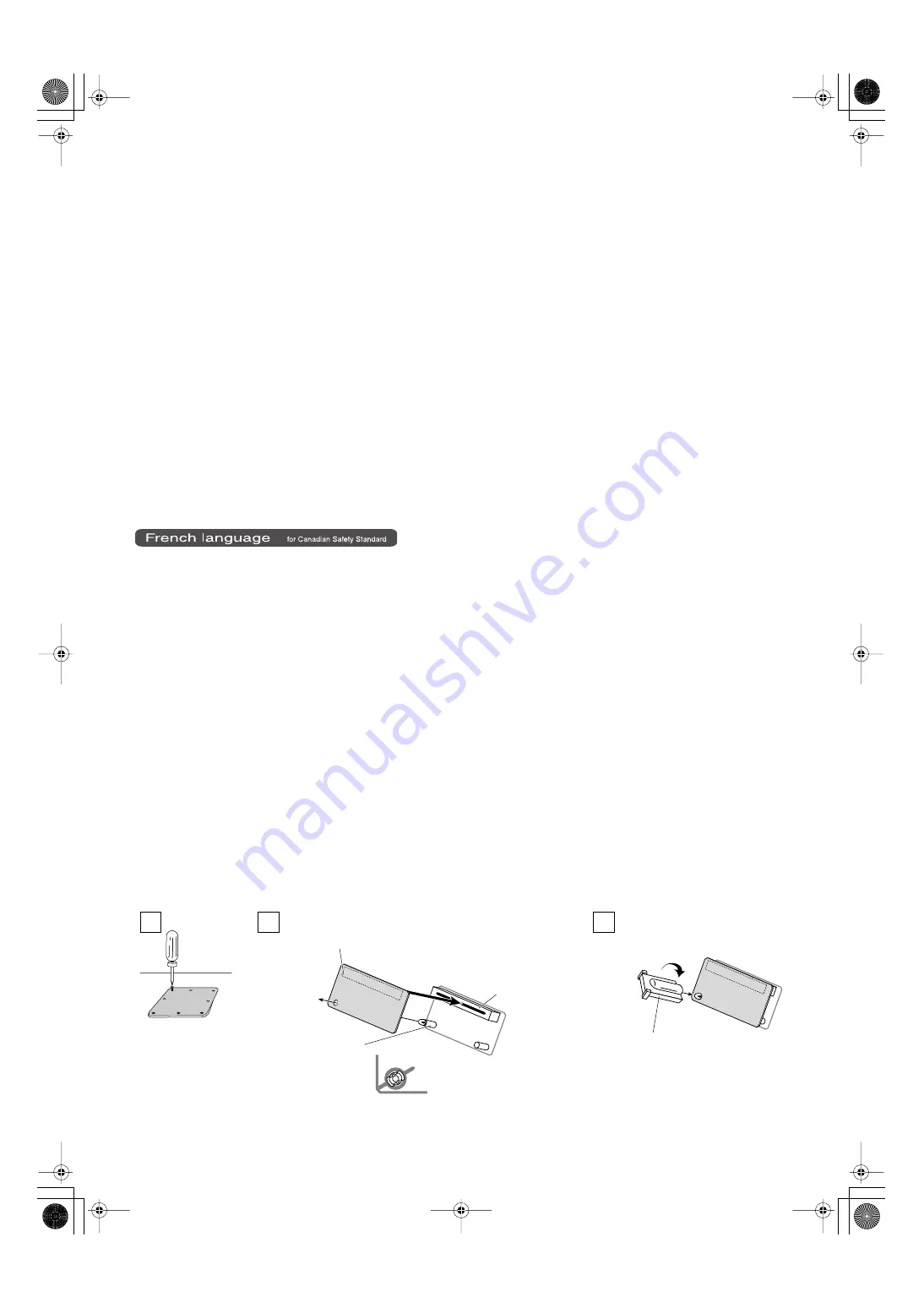
2.
Insert the Wave Expansion Board connector into a connector
for an SRX Series slot, while simultaneously inserting the
board holders into the holes in the Wave Expansion Board.
911
*
Do not touch any of the printed circuit pathways or connection
terminals.
912
*
Never use excessive force when installing a circuit board. If it doesn’t
fit properly on the first attempt, remove the board and try again.
3.
Use the supplied Installation Tool to turn the holders in the
LOCK direction, so the board will be fastened in place.
(To remove the Wave Expansion Board, turn the board holders
in the UNLOCK direction, and lift up the board.)
913
*
When circuit board installation is complete, double-check your work.
4.
Using the screws removed in Step 1, refasten the cover in its
original position.
5.
Check if the Wave Expansion Board is correctly installed.
*
If the “EXP” display cannot be selected (doesn’t appear) in the
Waveform Selection Screen (refer to the owner’s manual of the
instrument you use), remove the Wave Expansion Board and install it
properly.
* Éteindre l’instrument.
1.
Retirer le couvercle situé sur le dessus (ou á l’arrière) de
l’instrument.
2.
Inserer le connecteur de la carte dans un des creneaux pour
la serie SRX tout en enfoncant les supports a carte dans les
trous de celle-ci.
911(F)
*
Ne pas toucher aux circuits imprimés ou aux connecteurs.
912(F)
*
Ne jamais forcer lors de l’installation de la carte de circuits imprimés.
Si la carte s’ajuste mal au premier essai, enlevez la carte et
recommencez l’installation.
3.
Utiliser l’outil d’installation fourni pour tourner les clips de
retenue vers la position de blocage (LOCK) de façon á ce que
la carte soit retenue en place.
(Pour retirer la carte d’expansion Wave, tourner les clips de
retenue de la carte vers la position déblocage (UNLOCK) et
retirer la carte en la soulevant.)
913(F)
*
Quand l’installation de la carte de circuits imprimés est terminée,
revérifiez si tout est bien installé.
4.
Remettre la plaque a sa place et la fixer a l’aide des vis
enlevees a l’etape 1.
5.
S’assurer que la carte d’expansion Wave est installée
correctement.
*
S’il est impossible de sélectionner l’affichage “EXP” (il n’apparaît pas)
á l’écran de sélection Waveform (se reporter au guide du propriétaire
de l’instrument utilisé), retirer la carte d’expansion Wave et la
réinstaller correctement.
ウェーブ・エクスパンション・ボードの取り
付けかた
※ 使用機器の電源スイッチをオフにしてください。
1.
使用機器の上部、または背面にあるカバーをはずしま
す。
928
※ 本体を裏返す際は、ボタン、つまみなどを破損しないよ
うに、新聞や雑誌などを重ねて本体の四隅や両端に敷い
てください。また、その際、ボタン、つまみなどが破損
しないような位置に配置してください。
929
※ 本体を裏返す際は、落下や転倒を引き起こさないよう取
扱いにご注意ください。
2.
SRX シリーズ用のスロットのコネクターにウェーブ・エ
クスパンション・ボードのコネクターを差し込み、同時
に基板ホルダーをウェーブ・エクスパンション・ボード
の穴にはめ込みます。
911
※ 回路部やコネクター部には手を触れないでください。
912
※ 基板を無理に押し込まないでください。装着しにくい場
合、いったん基板を外してやり直してください。
3.
付属の固定用具で基板ホルダーを LOCK 方向に回し、
ウェーブ・エクスパンション・ボードを固定します。
(ウェーブ・エクスパンション・ボードを取り外すには、
基板ホルダーを UNLOCK 方向に回してから取り外しま
す。)
913
※ 取り付けを終えたら、正しく取り付けられていることを
再度確認してください。
4.
手順 1 で外したネジで、カバーを元通りに取り付けます。
5.
ウェーブ・エクスパンション・ボードの取り付けが正し
く行われたかを確認します。
※ ウェーブフォームの選択画面(使用機器の取扱説明書参
照)で EXP が選べない(表示されない)ときは、も
う一度ウェーブ・エクスパンション・ボードをつけ直し
てください。
2
1
3
ウェーブ・エクスパンション・ボード(SRXシリーズ)
Wave Expansion Board (SRX series)
Carte d'extension Wave (serie SRX)
コネクター
Connector
Connecteur
基板ホルダー
Board holder
Support à carte
取り付ける前に図のような向きに合わせます
Position them as shown before you install the board.
Avant l’installation, orienter les supports à carte tel qu’indiqué sur le schéma.
LOCK
Installation tool
Outil d'installation
固定用具
Screwdriver
ドライバー
Tournevis
SRX-12_je.book 5 ページ 2006年4月11日 火曜日 午前11時6分


