background image

Intelligent Dome Camera (6400AK Series) User Manual

11

structure of the Dome, and turn back to the initial position by the resetting program,
then vertically turn to 45

°

.When the Dome totally stops, the self-checking

finishes and it is ready to be under control.

c. You should wipe the dust and stain that on the transparent cast with a soft

flannel to prevent scratching the under hood.

d. Please let the screw be aligned from 3 holes in under hood and cover, and

fasten it with 3 M3 screws.

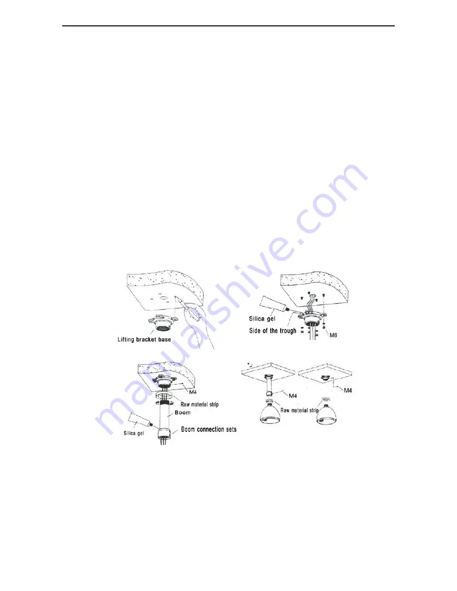
3.1.2 Intelligent Dome Camera Ceiling-mounted Bracket Installation

Ceiling-mounted Bracket Installation

Note: The ceiling which to be installed on should be solid and with no

delaminating. The bearing capacity of the installation location should be able to
afford at least five times of the total weight of the Dome, frame and pedestal, in
order to avoid image jitter caused by unstable installation

Note: If the camera used in outdoor, Waterproof seal should be in the camera

and bracket connecting part.

a. select a firm place on the ceiling that can withstand the weight of 5 kg.
b. With impact driller to lay a fixed hole on the mark holes.
c. Put the cable

communication line and video wire through the frame holes,

and set aside enough cable for connection.

d. Put the bracket secured to the ceiling then install the Dome Camera well.

Summary of Contents for 6400AK Series

Page 1: ...Intelligent Dome Camera 6400AK Series User Manual 6400AK Series Camera User Manual Version 1 0 ...

Page 2: ...ngth Rotating Speed Auto matching Technology 12 4 1 3 Auto overturn 12 4 1 4 Set and Call Preset Position 12 4 1 5 Set Cruising Function 12 4 1 6 Scanning between Two Spots 13 4 1 7 Home Place Function 13 4 1 8 Timed Events 13 4 2 Core Function 13 4 2 1 Zoom Control 13 4 2 2 Auto BLC 13 4 2 3 Auto WEB 13 4 2 4 Exposure 13 Ⅴ Camera OSD Setup 14 5 1 Operating instructions 14 5 1 1 Item Selections 14...

Page 3: ...mera Functions 29 5 8 1 Preset Points 29 5 8 2 Cruising 29 5 8 3 Close Auto Scanning 30 5 8 4 Long Distance Auto Scanning 30 5 8 5 Horizontal Scanning 30 5 8 6 Pattern Scanning 30 5 9 Exit 30 Ⅵ Trouble Shooting 31 Ⅶ Appendix Ⅰ Lightning and Surge Protection 32 Appendix Ⅱ Cleanness of Transparent Cover 34 Appendix Ⅲ General Knowledge of RS485 34 Appendix Ⅳ Relational Table of 24VAC Line Diameter an...

Page 4: ... t put the camera exposed under the rain and wet place Please be careful when you see the mark of Dangerous Voltage because it might be raise Electrical shock This provision is specifically designed to provide reasonable protection for this product in commercial areas which might be suffered malicious attack and it might be radiate radio energy If you didn t install and use following the user manu...

Page 5: ...d or other things penetrating into the camera or the camera could be damaged 6 To avoid affecting the usage of the Dome Camera please do not dismount its inner elements There are no user serviceable parts inside 7 The unit should be used in accordance with electrical standards Its RS 485 and Video Signal adopt TVS level anti thunder Keep the camera and signal cables away from high voltage cables P...

Page 6: ...as the functions of rapid location and continuous follow up scanning in a row but also achieves the real all round and no blind spot monitoring Besides it can automatically adapt to the environment and the objectives that are changing in terms of distance This camera adopts full digital control system and its design is quite exquisite and simple minimizing the connections between system components...

Page 7: ...tomatically change the channel according to the lens multiple Communication mode RS 485 Baud rate 2400 4800 9600 19200bps Rotate speed Horizontal 0 4 300 s 1 64 shift Rotate range horizontal360 rotation vertical 90 Auto flip function Auto flip when vertical Timed events Support 24 Pattern scanning Support 4 group Pattern scanning record Each group can record 100 orders and no time limited within o...

Page 8: ...e channel according to the lens multiple Communication mode RS 485 Baud rate 2400 4800 9600 19200bps Rotate speed Horizontal 0 4 300 s 1 64 shift Rotate range Horizontal 360 rotation vertical 90 Auto flip function Auto flip when vertical Timed events Support 24 Pattern scanning Support 4 group Pattern scanning record Each group can record 100 orders and no time limited within orders Auto scanning ...

Page 9: ...cratches made by hard objects might also result in a blurry image Please use a tender dry cloth or other substitutes to clean both the inner and outer side of the cover If the dirt is hard to clean a neutral detergent could be used any cleanser which is for luxury furniture can be used for the lower cover 3 1 1 Intelligent Dome Camera Wall mounted Bracket Installation Wall mounted Bracket Installa...

Page 10: ...r cord AC24V RS485 control wire is connected to RS485 control wire layer out Ensure that the positive and negative polarity of RS485 is properly connected A represents positive pole while B negative pole If RS485 is wrongly connected it could not control the Dome Camera a Check the polarity of the plug and socket and the connection of cable then power on b When the self checking starts the Dome wi...

Page 11: ...ing mounted Bracket Installation Note The ceiling which to be installed on should be solid and with no delaminating The bearing capacity of the installation location should be able to afford at least five times of the total weight of the Dome frame and pedestal in order to avoid image jitter caused by unstable installation Note If the camera used in outdoor Waterproof seal should be in the camera ...

Page 12: ... of tracking easier 4 1 3 Auto overturn When the operator turns the scene to the bottom vertically and continues pressing the control stick the camera will turn 180 horizontally and then upturn 90 to get a back view which provides a 180 whole course continuous monitor 4 1 4 Set and Call Preset Position Preset function is that the position parameters of horizontal angle vertical angle and lens focu...

Page 13: ...n finish the monitoring function in setting time 4 2 Core Function 4 2 1 Zoom Control Users can zoom in or out by using the WIDE and TELE key on the control keyboard to get an overall perspective or a close shot 4 2 2 Auto BLC The camera will divide the scene into six areas to realize the auto back light compensation In a bright environment it will auto compensate the dark object and adjust the li...

Page 14: ... Input Set preset position 1 9 to achieve number 1 9 input Set preset position 10 to achieve number 0 input Set preset position 11 to cancel the former input Set preset position 12 to cancel all numbers that input before Example 1 Input passward 8109 1 Set preset position 8 display 2 Set preset position 1 display 3 Set preset position 10 display 4 Set preset position 9 display Example 2 Input ID 1...

Page 15: ...ctions exit the menu at the same time 5 3 Check the Basic Information a Choose Information in current operation b Click Right button it will display the basic information of the camera c Click Left button to return the main menu 5 4 Enter the Core Setup a Choose Core Setup in current operation b Click Right button to enter into the core setting Main Menu System information Core Settings Camera Set...

Page 16: ...e carry out click the Right button and then carry out the first lens initialization immediately d Choose Everyday click the Right button and then carry out the first lens initialization automatically per 24 hours e Choose Every week click the Right button and then carry out the first lens initialization automatically per 168 hours f Choose Every Moth click the Right button and then carry out the f...

Page 17: ...rval is 3 240 sec 5 4 4 2 Recovering Auto Focus a Select the present operation Recovering Auto Focus b Click the Right button and then enter into the setting of Recovering Auto Focus c Click the Up Down buttons select the Recovering Auto Focus Mode as below Change Times The camera will recover auto focus after change times Rocker Click the rocker button it will recover auto focus Presets Click the...

Page 18: ...ose the Exposure option b Click the Right button and then enter into the exposure settings page 5 4 5 1 Auto a Choose the Auto option b Click the Right button and carry out the Auto Exposure Mode then enter Auto Exposure Intermittent time site c Setup the Auto Exposure Intermittent time 3 240S 5 4 5 2 Iris Priority a Choose the Iris Priority option b Click the Right button and carry out the Iris P...

Page 19: ...tton enter into the Privacy Area number input c Input the Privacy Area numbers 1 8 d Click the Right button enter into the Allow Forbidden selections of Privacy Area e Choose Allow Click the Right button and enter the core position of Privacy Area to setup f Set the core position of Privacy Area through the direction button then set preset position 12 to enter the Big and Small site of Privacy Are...

Page 20: ...he Auto WEB intermission time input d Input the numbers 3 240 Click the Right button to save and then return back 5 4 7 2 Indoor a Choose the Indoor option b Click the Right button select the indoor mode 5 4 7 3 Outdoor a Choose the Outdoor option b Click the Right button select the outdoor mode 5 4 7 4 Manual a Choose the Manual option b Click the Right button enter into the manual WEB setting NO...

Page 21: ...s a Choose the Address option b Click the Right button enter into the Address input c Input the address code click the Right button save the address settings the address code range is 0 255 then enter into the broadcasting address Allow Forbidden selections d Select Allow Forbidden click the Right button to save and then return back 0 is the broadcasting address Dome Camera Setting Configuration P...

Page 22: ...d Allow Forbidden selections b Select Allow in the current operation Click the Right button to enter into password input c Input the password figures for the 1 8 the factory default password is 88888888 Click the Right button to enter the password re enter d Re enter password figures for the 1 8 Click the Right button if this twice passwords is fit the new password will be saved and then exit othe...

Page 23: ...he configuration menu 5 5 1 6 Date a Choose the Date option b Click the Right button to enter the date setting c Set the parameters of Year Month Day Hour Minute Second click the Right button to save and then exit the year setting range is 0 99 5 5 1 7 Language a Choose the Language option to enter the language selection b Select language click the Right button to change the language then exit 5 5...

Page 24: ... b Click the Right button enter the cruising setting c Click Up Down buttons to select the menu of setting preview and testing 5 5 3 1 Setting a Choose the Setting option b Click the Right button enter the cruising group input c Input the cruising numbers 1 6 click the Right button to set cruising each cruising group can set 16 patrol points each patrol point set sequence is preset 1 128 speed 1 8...

Page 25: ...the Auto Scanning Allow Forbidden selections c Choose Allow click the Right button to enter the first point setting you can operate the controller to set the PTZ and mirror then set preset position 11 to return back or set preset position 12 to enter the second point setting d Operating the controller to set the PTZ and mirror of second point set preset position 11 to return back or set preset pos...

Page 26: ...s no limit between them e Set preset position 11 to return back Set preset position 12 to save and return back 5 5 4 4 Testing a Choose the Testing option b Click the Right button enter the scan testing c Click Up Down buttons select the scan testing mode as below Close Auto Scanning The dome camera execute the Close Auto Scan testing setup preset points 11 to exit testing Long Distance Auto Scann...

Page 27: ...oints a Choose the Preset Points option click the Right button and enter into the preset points numbers input b Input the preset points numbers click the Right button and enter into the home place waiting time setting 5 5 5 2 Cruising a Choose the Cruising option click the Right button and enter into the home place cruising setting b Input the cruising numbers click the Right button enter into the...

Page 28: ... events number input b Input numbers 1 24 click the Right button and enter into the timed events Allow Forbidden selection c Select Allow click the Right button enter into the timed events function selection d Select 1 128 Preset Points 1 6 Group Cruising 1 4 Group Pattern Scanning Close Long Distance two spots Scanning or horizontal Scanning click the Right button enter into the timed events then...

Page 29: ...u can preview all the setting that you have timed c Click the Left button Exit this setting and return to the dome camera setting 5 7 Restore the Factory Default a Choose the Restore the Factory Default option b Click the Right button the dome camera will restore the Factory Default Doesn t restore the password and language selection 5 8 Dome Camera Functions a Choose the Dome Camera Functions opt...

Page 30: ...uto Scanning option b Click the Right button call the Close Auto Scanning then exit the menu at the same time 5 8 4 Long Distance Auto Scanning a Choose the Long Distance Auto Scanning option b Click the Right button call the Long Distance Auto Scanning then exit the menu at the same time 5 8 5 Horizontal Scanning a Choose the Horizontal Scanning option b Click the Right button call the Horizontal...

Page 31: ...required power supply Put power supply close to Dome Camera Normal self check but no images Wrong connection of video Correct Bad connection of video Eliminate Camera damaged Replace Normal self check but out of control Wrong connection of signal control cable Correct Dome ID setup is wrong Reselect Protocol or communication baud rate is not matched Adjust protocol to match with the controller and...

Page 32: ...rangement must be adopted in open area and steel tube must adopt one single connect earth The overhead ground arrangement is absolutely forbidden In the intense thunderstorm or high induced voltage area e g High Voltage Junction Box such methods as the installation of extra superpower lightning protection equipments or lightning rod must be adopted The design of outdoor device and the lightning pr...

Page 33: ...elligent Dome Camera 6400AK Series User Manual 33 PIC 1 This product use the dome shell connecting ground if you don t use it lightning ground jumper cap can be changed to lightning to connect the external ...

Page 34: ...ing take the lower cover down by holding the outer ring carefully avoiding direct touch the acidic sweat on one s finger might corrode the coating of the cover And the scratches made by hard objects might also result in a blurry image Please use a tender dry cloth or other substitutes to clean both the inner and outer side of the cover If the dirt is hard to clean a neutral detergent could be used...

Page 35: ...isy chained ways should be adopted among devices with 120Ω terminal resistors at both ends The connection can be simplified as that in picture 4 but D distance should not be more than 7 meters PIC 3 PIC 4 b The connection mode of device terminal 120Ω There are device terminal resistances on controller board which have two connection modes One is the factory default connection mode without 120Ω res...

Page 36: ...g requirements of RS 485 industrial standard so the problems like signal reflex and the decrease of anti jamming capability easily occur which may reduce the reliability of controlled signal The phenomenon reflected is that balling machine is completely or discontinuously out of control or that it cannot stop running To solve these problems we propose to use MC 2080 Rs485 distributor because this ...

Page 37: ...d be 0 8000mm Wire radii mm Distance feet m Power 0 8000 1 000 1 250 2 000 10 283 86 451 137 716 218 1811 551 20 141 42 225 68 358 109 905 275 30 94 28 150 45 238 72 603 183 40 70 21 112 34 179 54 452 137 50 56 17 90 27 143 43 362 110 60 47 14 75 22 119 36 301 91 70 40 12 64 19 102 31 258 78 80 35 10 56 17 89 27 226 68 90 31 9 50 15 79 24 201 61 100 28 8 45 13 71 21 181 55 110 25 7 41 12 65 19 164...

Page 38: ...0196 0 060 42 46 0 00283 0 070 41 45 0 00385 0 080 40 44 0 00503 0 090 39 43 0 00636 0 100 38 42 0 00785 0 110 37 41 0 00950 0 130 36 39 0 01327 0 140 35 0 01539 0 160 34 37 0 02011 0 180 33 0 02545 0 200 32 35 0 03142 0 230 31 0 04115 0 250 30 33 0 04909 0 290 29 31 0 06605 0 330 28 30 0 08553 0 350 27 29 0 09621 0 400 26 28 0 1237 0 450 25 0 1602 0 560 24 24 0 2463 0 600 23 23 0 2827 0 710 22 22...

Page 39: ...0000 32 00110110 54 00001011 11 00100001 33 00110111 55 00001100 12 00100010 34 00111000 56 00001101 13 00100011 35 00111001 57 00001110 14 00100100 36 00111010 58 00001111 15 00100101 37 00111011 59 00010000 16 00100110 38 00111100 60 00010001 17 00100111 39 00111101 61 00010010 18 00101000 40 00111110 62 00010011 19 00101001 41 00111111 63 00010100 20 00101010 42 01000000 64 00010101 21 00101011...

Page 40: ...1100 124 10100110 166 01010011 83 01111101 125 10100111 167 01010100 84 01111110 126 10101000 168 01010101 85 01111111 127 10101001 169 01010110 86 10000000 128 10101010 170 01010111 87 10000001 129 10101011 171 01011000 88 10000010 130 10101100 172 01011001 89 10000011 131 10101101 173 01011010 90 10000100 132 10101110 174 01011011 91 10000101 133 10101111 175 01011100 92 10000110 134 10110000 17...

Page 41: ...1000011 195 11011000 216 11101101 237 11000100 196 11011001 217 11101110 238 11000101 197 11011010 218 11101111 239 11000110 198 11011011 219 11110000 240 11000111 199 11011100 220 11110001 241 11001000 200 11011101 221 11110010 242 11001001 201 11011110 222 11110011 243 11001010 202 11011111 223 11110100 244 11001011 203 11100000 224 11110101 245 11001100 204 11100001 225 11110110 246 11001101 20...

Reviews: