20
Horizontal System (Time Base)
to +5 divisions, 0 is the middle of the screen and the stan-
dard setting).
5 .3 Capture modes
The capture modes are selected by pushing the key AC
-
QUIRE, this opens a display menu which offers the basic
modes of capture:
5 .3 .1 Refresh
In this mode the signals are captured and displayed.
5 .3 .2 Roll
This
acquisition mode is intended specifically for very
slow signals, with the untriggered signal „rolling“ across
the screen from right to left (requires signals slower than
200 kHz). The HMO uses a ring buffer to store the signal
values in
roll mode. Simply put, the instrument writes the
first division to the first storage space, the second division
to the second storage space, etc. Once the storage is full,
the instrument overwrites the first storage space with the
data of the most recent measurement value. This creates a
„ring“ or cycle run, similar to a ticker.
5 .3 .3: ENVELOPE
In this mode, the display includes the normal capture of
each signal and the maximum as well as the minimum va
-
lues of each capture. Over time, this creates an envelope
surrounding the signal.
5 .3 .4: AVERAGE
In this mode, you can use the
universal knob in the Cursor/
Menu section of the control panel to set the number of sig
-
nal periods for averaging, available in powers of 2 from 2
to 1024 (requires repetitive signals).
5 .3 .5: FILTER
In this mode, you can activate a low pass filter with ad-
justable cut off frequency to suppress unwanted high fre
-
quency interferences. The cut off frequency can be set
based on the sampling frequency. The minimum setting is
1/100 of the sampling frequency and the maximum value
is 1/4 of the
sampling rate. You can select this setting with
the universal knob.
The second menu page is accessed by pushing the soft
key next to the menu „Page 1I2“, here, extended func-
tions are available:
5 .3 .6 Peak Detect
This mode is used for very large time base settings to de
-
tect even short signal changes. You can also deactivate
this function within the menu or you can select the auto
-
matic switching mode. The following conditions must be
met to activate the PEAK DETECT mode:
❙
Function HIGH RESOLUTION is deactivated
❙
None of the serial or parallel buses are active
The ZOOM feature is not available in the roll mode (also refer to Chap.
5.5 ZOOM Function)
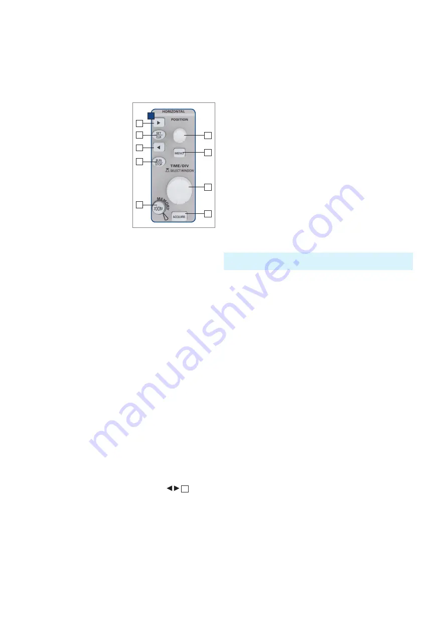
5 Horizontal Sys
-
tem (Time Base)
As well as
time base settings,
the horizontal system compri-
ses the selection of the trig
-
ger position, the zoom func-
tions and the available modes
of signal capture, the control
for the marker function and
the search fcuntions.
The knobs are used for the
adjustment of the time base
speed and the trigger posi
-
tion. The signal capture mo
-
des are selected in the respec
-
tive menus. There is a key pro
-
vided for activating the
zoom
function.
5 .1 Capturing modes RUN and STOP
The capturing modes can be selected with the key RUN/
STOP. In RUN mode signals will be continuously captu
-
red; depending on the
trigger conditions selected, and dis-
played, erasing the previously captured ones. If it is desi-
red to store and further analyze a signal and to prevent it
being overwritten, capture must be stopped by pushing
the RUN/STOP key. While in STOP mode capture is disab
-
led and the key will light up red.
5 .2 Time base adjustments
The large knob in the Horizontal section of the control pa-
nel is used for the selection of the time base speed. The
time base speed is displayed in the upper left hand corner
above the graticule. (e.g. „TB:500 ns“) To the right there is
the display of the trigger time position with respect to the
normal position. The normal trigger position is in the cen
-
ter of the graticule such that 50 % of the signal display is
before and 50 % is after this trigger position. The X Posi
-
tion knob allows continuous adjustment of the X position.
The available maximum values depend on the time base
setting. By pushing the key SET/CLR the value will be re
-
set to its reference position. The arrow keys
37
allow
you to change the X position by a fixed amount of 5 divisi-
ons in the respective direction. If marker or search function
is chosen the arrow keys together with the SET/CLR but
-
ton are used to navigate through and set/clear marker. The
key menu opens a menu which allows you to set the X po
-
sition to its minimum and maximum positions or chose the
marker function by just a key touch. In addition, there is a
submenu NUMER.INPUT which allows entry of an arbit
-
rary X position. Within this menu the search functions can
be activated and set. In addition the time reference can
be set here (position for the trigger point in time, from -5
Fig. 5.1: Control panel of the
horizontal system
37
D
38
37
41
39
42
43
44
40


