MCX4D Operating Manual.doc
2018-07-20
12/15
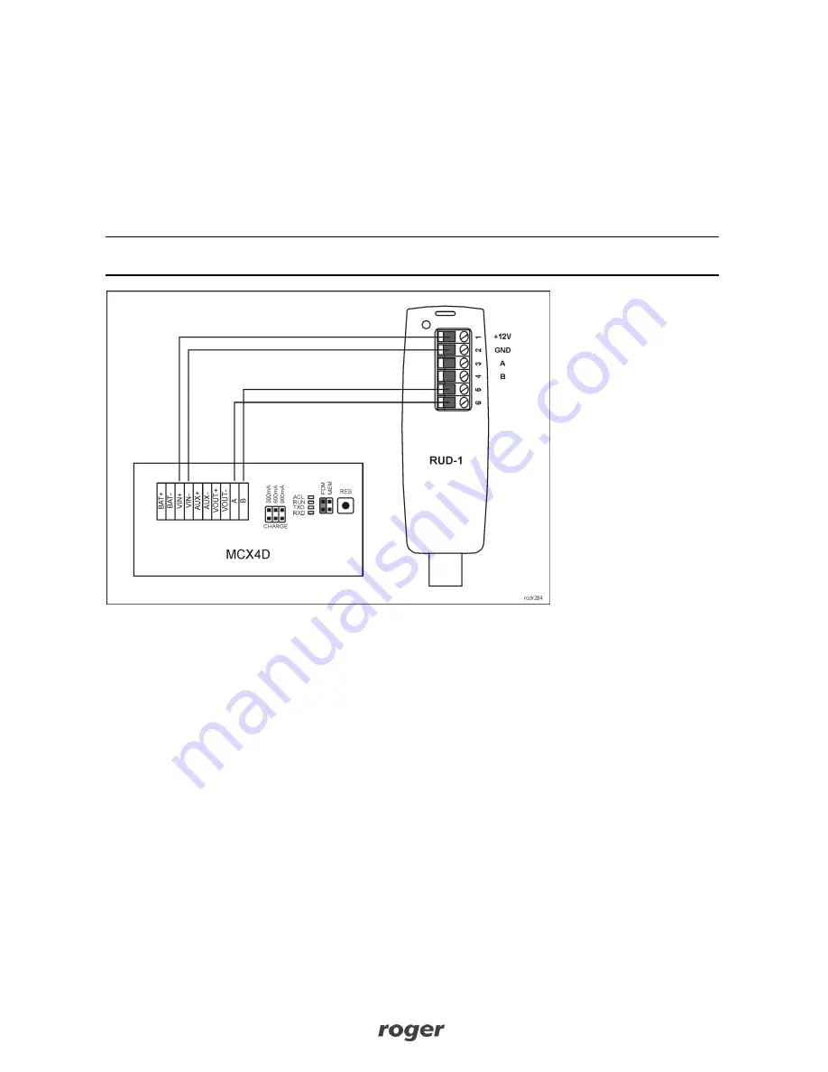
Connect the device to RUD-1 interface according to fig. 9
Place jumper on FDM pins
Press RES button
Start RogerVDM software
In the top menu select
Tools->Update firmware
Select device type and communication port with RUD-1 device as well as indicate firmware file
(*.hex)
Click
Update
and proceed according to displayed messages
After firmware upload, remove jumper from FDM pins and press RES button
Note: When firmware is updated then it is necessary to configure the device with RogerVDM software or
start memory reset procedure and manually define the address of device.
Fig. 9 Connection of expander to RUD-1 (firmware update)
Installation
Enclosure with DIN rail is recommended for installation of MCX4D expander. All electric connections must
be done without voltage on wires/terminals and with power supply disconnected. Optionally, DIN rail
mounting clips can be removed and the expander can be installed on flat surface. It is recommended to
install the expander in the same enclosure as PSU. The cross section of power supply wires must be
adequate as to avoid voltage drop greater than 200mV for rated load. It is recommended to use cables with
minimal 1mm
2
cross section and maximal 30 cm length. Such cables are offered with PSxD series power
supply units. Prior to expander connection to the controller specify RS485 address and configure other
electric parameters if necessary. The expander is configured within low level configuration by means of
RogerVDM. Default address of factory new device is ID=100.


