MCX16-AP Operating manual.doc
2018-11-29
9/12
Short CLK and DTA lines.
Restore power supply (all LED flashing) and wait min. 5s.
Remove connection between CLK and DTA lines (LEDs stop flashing, LED8 is ON).
Start RogerVDM program.
Select device
MCX16-AP v1.x
, firmware version and
Ethernet
communication channel.
Enter device IP address and communication key (by default respectively 192.168.0.81, admin).
Click
Connect
button, the program will establish connection and automatically open configuration
window
.
In configuration window click
Send to file...
button and backup settings.
In the top menu select
Tools->Update firmware
Click
Select file
, indicate firmware file (*.frg) and click
Update
button.
Start low level configuration or restore it from backup file.
Firmware update with memory card
Switch power supply off.
Press and remove memory card from expander.
Use memory card reader to connect the card to computer.
Copy the new firmware (*.frg) to the memory card and rename it as FW.BUF.
Insert the memory card into expander socket.
Restore power supply and expander will automatically start the firmware update process. During
this process, which usually takes 10s, LED2 is ON while LED3 is flashing.
Once the update is finished the FW.BUF
file is automatically erased and expander returns to
service mode (LED8 is steady ON).
Start RogerVDM program and make low level configuration.
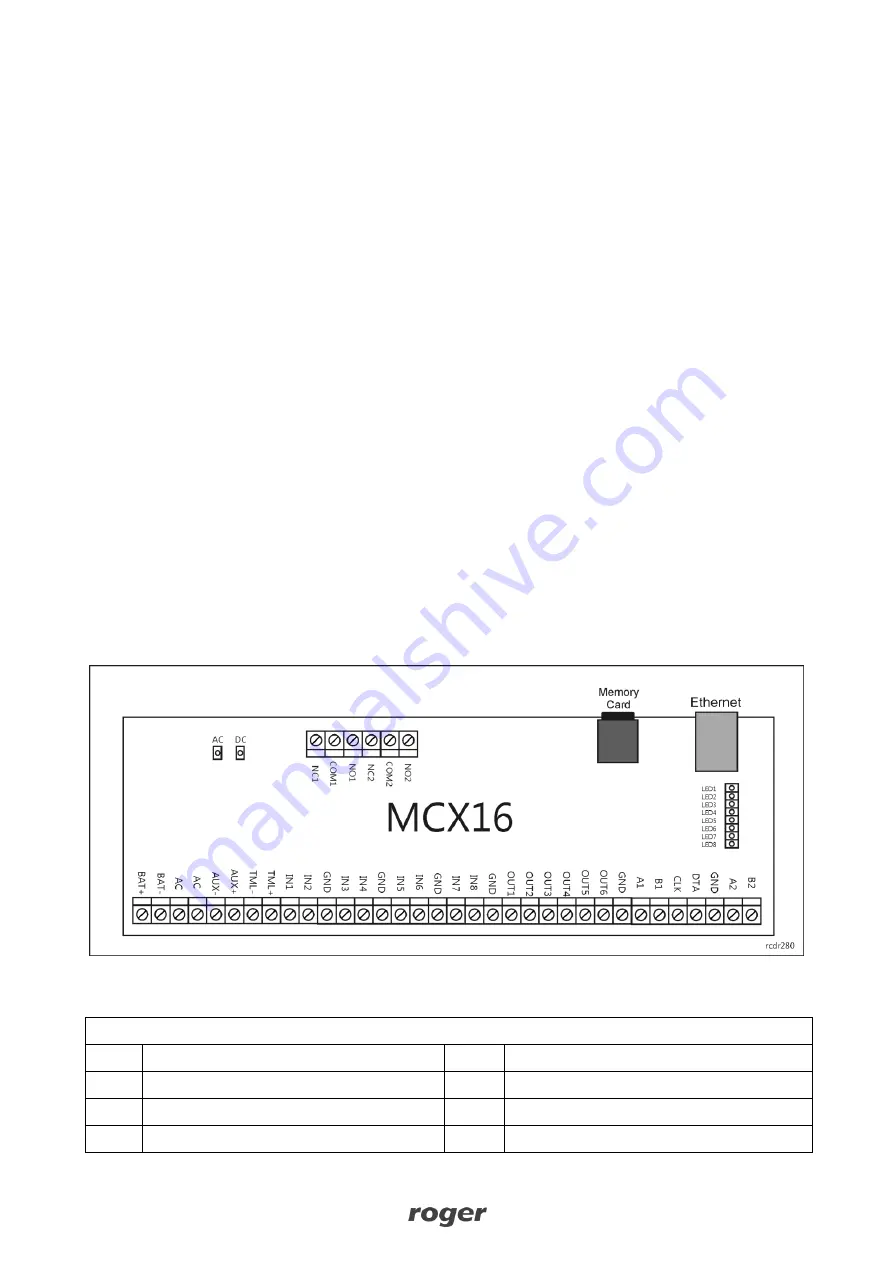
Installation
Enclosure with DIN rail is recommended for installation of MCX16-AP expander. All electric connections
must be done without voltage on wires/terminals and with power supply disconnected. Optionally DIN rail
mounting clips can be removed and the expander can be installed on flat surface. Prior to expander
connection to the controller make low level configuration with RogerVDM software.
Fig. 8 MCX16-AP board
Table 2. MCX16-AP terminals
Term.
Description
Term.
Description
NC1
REL1 relay output (NC)
IN5
IN5 input
COM1 REL1 relay common terminal
IN6
IN6 input
NO1
REL1 relay output (NO)
GND
Ground


