ADL-2 User Manual.doc
2021-11-03
Page 11 of 12
I
NSTALLATION
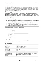
The lock is designed for mounting in door with 38 to 75mm thickness, with mortise lock installed and
with 72mm handle spacing. Prior to installation make sure that door cylinder is long enough. The lock
is delivered with two handle pins and two sets of bolts with different length. In case of door with 55m
or greater thickness, longer bolts should be used.
Power supply
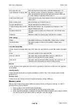
Lock is supplied from 4 x AAA batteries. Assuming average 10 openings of lock per day, alkaline
batteries enable 1 year operation of the lock. Low battery level is signalled by red LED indicator with
battery icon (in the bottom part of keypad panel). The indicator will signal low battery level only when
PIN is entered and then it switches off.
Lock installation
·
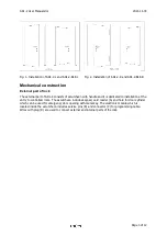
Make holes in door using drilling template.
·
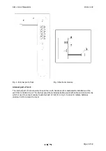
Lead battery wires (fig. 5, pos. G) through hole and then connect with wires from external part
of lock (fig. 3, pos. E).
·
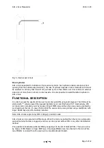
Make sure that handle pin hole is positioned in such way that marker (red dot) indicates door
top hinge (fig. 7) and then install handle pin inside the lock.
·
Install 4 x AAA batteries in the pack.
·
Mount escutcheon and verify the operation of internal handle and door cylinder, particularly if
handle latch is retracted when metal key is used.
Note: Preserve metal key for emergency opening of door.
Fig. 7. Proper installation of handle mechanism
Specification
Parameter
Value
Power supply
4 x AAA (LR03) alkaline batteries
Battery life
1 year with 10 entries per day
Door thickness
38 – 75 mm
Handle spacing
72 mm
Built-in card reader
ISO/IEC 14443A MIFARE®
Environmental class
(acc. to EN 50131-1)
Class I, indoor general conditions, temperature: +5°C to +40°C,
relative humidity: 10 to 95% (no condensation)
IP code
IP40


