


906-0002-00 Rev 9 EN
2002
Rofin-Sinar UK Ltd
General Description 2 - 2
Depending on the configuration of the resonator, there may also be
diffraction effects due to the output optic of the resonator. This can produce
secondary lobes on the main output beam that need to be scraped or
filtered out. This is achieved by the use of a spatial filter.
After beam correction and spatial filtering the beam quality from a slab
laser is ideal for any material processing operation that requires excellent
mode quality and stability.
2.1 Laser Head Layout
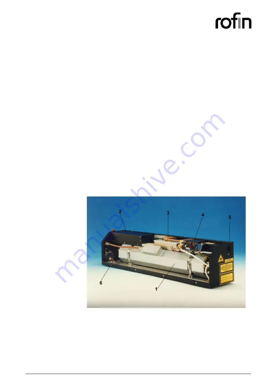
Figure 2.1-1 shows the layout of the inside of the laser head housing. After
exiting the Laser Tube (1), the laser beam is turned through 45 degrees by
a plane turning mirror and is directed into the Beam Correction Module (2).
Inside the Beam Correction Module, a second plane turning mirror directs
the laser beam towards an angled spherical reflective element, which
corrects the shape of the beam to make it round and also focuses the
beam into the spatial filter. The spherical mirror then deflects the beam
towards a plane mirror, which directs the beam into the Spatial Filter
Module (3).
The Spatial Filter scrapes off any unwanted secondary lobes on the laser
beam. After exiting the Spatial Filter the beam enters the Safety Shutter
Module (4). The Safety Shutter is used to block off any unwanted laser
output using a rotary solenoid and a reflective blade. When in place, the
Safety Shutter deflects the beam into a thermal dump.
Figure 2.1-1
Laser Head Layout (not to scale)
When the laser beam exits the Safety Shutter Module it is directed towards
the Final Output Window (5). Depending on the specific requirements of
the customer, this transmissive element can be either a plane window or a
lens.
The Laser Tube, Spatial Filter and Shutter Module are all water cooled and
the water flow is monitored by a Flow Switch (6).


