INSTALLING THE CFR SENSOR
Note: Failure to adequately prepare the feeder’s
surface properly may result in a Constant Feed
Rate (CFR) sensor that will not bond to the
feeder. The sensor should not be mounted until
step C-6.
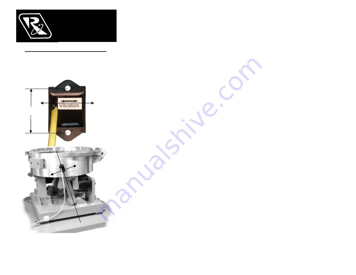
Fig. 2 The arrow shows the direction of vibration
which is at a right angle to the spring pack.
A. ORIENT THE SENSOR
so that its sensitive axis
is in the same direction as the vibration of the
feeder. The double-ended arrow in figure 1 shows
the sensor’s sensitive axis. Align the sensitive axis of
the sensor in the same direction as the vibration (see
figure 2). The sensor must be oriented correctly for
proper operation.
B. CHOOSE A LOCATION
for mounting the sensor
on the feeder that is smooth and that will allow the
adhesive on the sensor to bond. Avoid mounting the
sensor over ridges and bumps which can reduce the
ability of the adhesive to stick to the feeder. The
correct location will also have enough space for the
sensor’s cable to hang straight down without touching
anything else.
C. SURFACE PREPARATION
of the feeder is crucial
for proper bonding between the sensor and the feeder.
Please follow these steps completely.
1) The feeder should be kept between 70
and 100
F
for ideal tape application.
2) Clean a three and one-half inch circular area with a
solvent like isopropyl alcohol that will not leave a
residue. As a rule of thumb, the area can be
considered clean when after cleaning the area with a
solvent-saturated, white paper-towel, the towel is as
clean as it was before wiping.
3) Using a good amount of pressure, polish the
cleaned, circular area of the feeder using a scratch
pad or steel wool. Repeat step 2, and then go to
step 4.
4) Wipe the cleaned surface with an alcohol wipe or
with a 50/50 isopropyl alcohol/water combination.
5) Dry the surface thoroughly using a low lint cloth or a
clean paper towel.
6) Remove the vibration sensor from its protective
packaging. Remove the liner from the adhesive
backing. Avoid touching the tape. Align the sensor
as shown in figures 1 and 2. Apply the vibration
sensor to the prepared area of the feeder. Press the
sensor very firmly onto the feeder surface for at least
10 seconds.
7) Allow the vibration sensor at least 20 minutes to
cure before operation. Note: It takes 72 hours for
the adhesive to fully cure at 70
F.
Alternatively, #8 or M4 screws can be used to mount
the sensor to the feeder. The mounting holes are
1.375” (3.49cm) apart.
D. ROUTE THE SENSOR CABLE
to protect it from
strain due to vibration. The cable that attaches to the
sensor will not break from normal vibration; however,
some care should be used when routing the sensor
cable from the sensor to the control. The cable should
hang straight down from the sensor without touching
the feeder bowl or anything else. Then, the
sensor cable should curve towards the power
control with a bend radius larger than 3 inches.
Use a cable tie and an adhesive-backed mount to
attach the sensor cable to the side of the drive
base. See Figure 2. Clean the mounting area
before applying the adhesive-backed mount.
E. CONNECT THE SENSOR
to the control. If
needed, connect the sensor cable’s brown wire to
“+ACCEL” on TB2. The blue wire connects to the
“–ACCEL” on TB2.
F. SELECT THE SENSOR
in the software settings
of the control menu. See the Control Menu Layout
page for a visual layout of the program menu.
1) Press and hold the “Enter” key to enter the
main menu.
2) With “Power Settings” displayed, press the
“Enter” key to get into the submenu.
3) Arrow “Down” to select the “Amplitude Source”
submenu.
4) Press the “Enter” key, and Arrow “UP” to select
“Auto Tracking” from the adjustments.
5) Press the “Back” key twice to get back to the
main menu.
6) Next, arrow “Down” to the “Frequency Settings”
selection.
7) Press the “Enter” key to get into the submenu.
8) Arrow “Down” to select the “Frequency Mode”
submenu.
9) Press the “Enter” key, and Arrow “UP” to select
“Auto Tracking” from the adjustments.
10) Press the “Back” key three times to get back
to the normal running display.
G. PERFORM AUTO SCAN
of the vibratory
feeder. See the Control Menu Layout page for a
visual layout of the program menu.
1) Press and hold the “Enter” key to enter the
main menu.
2) Arrow “Down” to select the “Frequency”
submenu.
3) Press the “Enter” key, and Arrow “UP” three
times to select “Auto Scan” from the adjustments.
4) Press the “Enter” key to perform an automatic
frequency scan.
Warning: Avoid dropping the sensor on a hard
surface. Damage could occur.
RODIX, INC.
Toll Free (800) 562-1868
E-mail [email protected], rodix.com
© 2005, 2020 RODIX INC. 123-215 VF-9 CFRsensor .doc
RODIX INC.
FEEDER CUBE
VF SERIES CFR SENSOR
CONSTANT FEED RATE
P/N 123-215
Sensitive
Axis of
Vibration
Fig. 1
Actual Size
1.375”
P/N 123-215


