T1, T2 (TB502)
Connections to optional external tachometer.
Enclosed drive terminals
L1 (terminal 1)
Hot terminal for AC line voltage.
L2/115 (terminal 2)
Neutral terminal for 115 VAC line voltage.
L2/230 (terminal 3)
Neutral terminal for 230 VAC line voltage.
F1, F2 (terminals 4 and 5)
Field coil connections (shunt wound motors only). Field
voltage is 100/200 VDC.
A1, A2 (terminals 6 and 7)
Connections to motor.
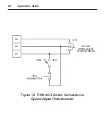
COM (terminal 8)
Circuit common (-) for external reference signal.
REF (terminal 9)
Signal (+) lead for external reference signal.
77
Troubleshooting
Summary of Contents for RELIANCE ELECTRIC DC3N Series
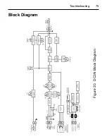
Page 83: ...75 Troubleshooting Figure 20 DC3N Block Diagram Block Diagram ...
Page 90: ...NOTES 82 ...
Page 91: ...NOTES 83 ...


