5-14
Using the I/O
PowerFlex® 755 Drive Embedded EtherNet/IP Adapter User Manual
Publication 750COM-UM001A-EN-P
PLC-5, SLC 500, and
MicroLogix 1100 Example
Adapter Parameter Settings
For the adapter settings used for the example ladder logic program in
this section:
Understanding Controller Data Table Addresses
Since PLC-5, SLC 500, and MicroLogix 1100 controllers are 16-bit
platforms being used with the 32-bit embedded EtherNet/IP adapter, the
data will be transposed from the least significant word (LSW) to the
most significant word (MSW) in the controller.
When the I/O was configured (
), an available data table file
(N20) was used.
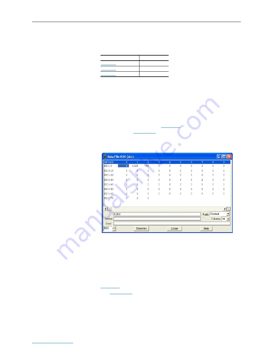
shows the entire data file address structure
for this example.
Figure 5.11 Data File Table for Example Ladder Logic Program
Important: The N20:0 data table address in this example is used to set
a control timeout value (in seconds) which determines how
long it will take the adapter to detect a communication loss.
Enter a valid value between 1 - 32767 for N20:0. A value of
zero (0) is not valid, since it disables the timeout and all I/O
messages (Logic Command/Status, Reference/Feedback,
and Datalinks) intended for the drive will not execute.
shows the I/O definitions as they relate to the N20 data table
file (
) being used in this example.
For PowerFlex 750-Series drives, which contain both DINT (32-bit
format) and REAL (floating point format) data types, you will always
read from and write to the LSW data table address in the controller first.
Then if the data value exceeds 16 bits, the remaining value will be in the
MSW data table address.
Refer to the Table on… Controller Type
PLC-5
SLC 500
MicroLogix 1100


