8
MP-Series Low Inertia Servo Motor Installation Instructions
Publication MP-IN002C-EN-P - April 2009
Install the Motor
All motors include a mounting pilot for aligning the motor on the machine.
Preferred fasteners are hardened steel. The installation must comply with all local
regulations and use equipment and installation practices that promote safety and
electromagnetic compatibility.
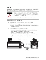
Verify Connector O-ring and Backshell Seal
An O-ring on the feedback connector, and a backshell seal on the feedback and
power/brake connectors are necessary to achieve the maximum environmental
rating. Verify the seal and O-rings are installed as described.
ATTENTION
Unmounted motors, disconnected mechanical couplings, loose shaft keys, and
disconnected cables are dangerous if power is applied.
Disassembled equipment should be appropriately identified (tagged-out) and access to
electrical power restricted (locked-out).
Before applying power to the motor, remove the shaft key and other mechanical couplings
which could be thrown from the shaft.
Failure to observe safety precautions could result in personal injury.
ATTENTION
Make sure that cables are installed and restrained to prevent uneven tension or flexing at
the cable connections.
Excessive and uneven lateral force on the cable can result in the environmental seal
opening and closing as the cable flexes.
Failure to observe safety precautions could result in damage to the motor and its
components.
Location Verify
•
An O-ring is mounted on the external surface of
the feedback connector and the power/brake
connector.
•
The O-ring is undamaged, not twisted, and rests
in the groove near the rear of the connector.
•
A backshell seal covers the joint inside the
feedback and power/brake housings. It seals the
joint between the backshell and the housing of
the connector.
•
The backshell seal is undamaged, and it is fully
seated against the face of the backshell.
O-ring
Groove Reserved For
Quick-lock Plug
Backshell Seal Inside
Feedback and
Power/Brake
Connector Housing


