Rockwell Automation ARMORSTART Programming Manual Download Page 12

12

Rockwell Automation Publication 280E-PM001A-EN-P – August 2011

Chapter 2

        ArmorStart

®

 EtherNet/IP

 Communications & Control Programming Manual

Port Configuration 

– ONLINE

Network

 – ONLINE

The last five tabs in the list will not display information until the ONLINE 
connection has been established with the ArmorStart. The General, Connection, 
and Parameters tabs will be discussed first because they are used to define 
OFFLINE settings so that connection with the ArmorStart can be established.

Offline Connection

General Tab

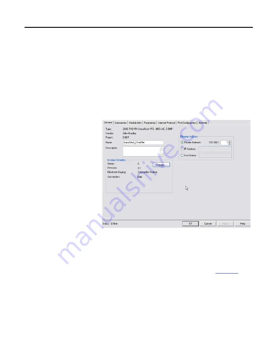
Click on the General tab to display the following:

This tab allows you to name your module, which should be descriptive and 
representative of the module.  The IP Address of the module must also be input 
so that communication can be established. The IP Address should be the one 
defined using the BootP/DHCP Server, the Rotary Network Address Switches 
or the ArmorStart internal web server. For more information on how to set-up 
the IP address of the ArmorStart using these methods, check 

Appendix B

For the majority of cases, the 

Host Name

 and 

Module Definition

 section of this 

tab do not require any adjustment. Changes to either of these should only be 
made if you are familiar with the functionality of each of these sections.

Summary of Contents for ARMORSTART

Page 1: ...PROGRAMMING MANUAL ARMORSTART ETHERNET IP COMMUNICATIONS CONTROL BULLETINS 280E AND 284E ...

Page 2: ...d with any particular installation Rockwell Automation Inc cannot assume responsibility or liability for actual use based on the examples and diagrams No patent liability is assumed by Rockwell Automation Inc with respect to use of information circuits equipment or software described in this manual Reproduction of the contents of this manual in whole or in part without written permission of Rockwe...

Page 3: ...the Bulletin 280E or Bulletin 284E ArmorStart EtherNet IP unit using Ladder Logic in RSLogix 5000 This method of control occurs over the EtherNet network using a Programmable Logic Controller PLC There is also a section which focuses on utilizing RSLogix 5000 to configure the ArmorStart via the AOP parameter list The Hand Off Auto HOA control in Bulletins 280E and 284E ArmorStart units is discusse...

Page 4: ...4 Rockwell Automation Publication 280E PM001A EN P August 2011 ArmorStart EtherNet IP Communications Control Programming Manual Notes ...

Page 5: ...to Access the ArmorStart Ethernet IP Internal Web Server 23 Web Server Functionality 25 Parameters 26 Diagnostics 27 Setting Up the Device Password 28 Setting Up the E mail Notifications 30 Chapter 4 ArmorStart Bulletin 280E Full Voltage Starter 31 Control via RSLogix 5000 Ladder Logic 31 Configuring the ArmorStart using the Parameter List in RSLogix 5000 38 Hand Off Auto HOA Control 41 Diagnostic...

Page 6: ...nk Patterns 69 Bulletin 284E Blink Patterns 70 Bulletin 280E Trip Status 71 Bulletin 284E Trip Status 72 EtherNet IP Indicators 74 Appendix B Configuring EtherNet IP Ports 77 Using the BootP DHCP Server 77 Using the Rotary Network Address Switches 77 Using the ArmorStart Internal Web Server 79 Appendix C Type 1 Reset of an ArmorStart EtherNet IP 83 ...

Page 7: ...ofile AOP to RSLogix 5000 It is assumed that you have downloaded and installed the AOP so that the RSLogix 5000 software can fully support the ArmorStart Ethernet IP The AOP can be downloaded from http support rockwellautomation com controlflash LogixProfiler asp 1 Open RSLogix 5000 by double clicking on the icon on your desktop 2 Select File New to create a new project ...

Page 8: ...ming Manual 3 Enter the name of the project and select your controller from the Type drop down menu For this example a Cat No 1769 L35E and software revision 19 will be used Then click OK 4 To add a new module to the tree right click on Ethernet and select New Module This allows you to add a new ArmorStart to the Logix Project ...

Page 9: ... your application and click OK 6 The AOP is shown below Enter a Name for this ArmorStart and an Ethernet address For this example the Private Network setting will be used This should be set to match the IP address switch setting on the ArmorStart Then press OK Note Refer to Using the Rotary Network Address Switches in Appendix B to set an IP address on the device ...

Page 10: ...10 Rockwell Automation Publication 280E PM001A EN P August 2011 Chapter 1 ArmorStart EtherNet IP Communications Control Programming Manual Notes ...

Page 11: ...Before the walkthrough is started the RSLogix 5000 software should be open and an AOP displayed as shown below The screenshot above displays that the AOP has seven tabs that can be used to configure and or monitor your ArmorStart The following lists the tabs and whether or not they are editable with the controller when OFFLINE ONLINE or both General OFFLINE Connection OFFLINE Module Info ONLINE Pa...

Page 12: ...lick on the General tab to display the following This tab allows you to name your module which should be descriptive and representative of the module The IP Address of the module must also be input so that communication can be established The IP Address should be the one defined using the BootP DHCP Server the Rotary Network Address Switches or the ArmorStart internal web server For more informati...

Page 13: ...terval assigned in the RPI In the majority of cases the default 20 ms should be the optimal setting If you check the Inhibit Module option connection to controller tags will be broken The Major Fault on Controller if Connection Fails While in Run Mode option should be checked to ensure that the controller processes the connection fault with the ArmorStart The Use Unicast Connection over EtherNet I...

Page 14: ...lletin 280E groups depending on the ArmorStart These Setup groups are the minimum required parameters to get the ArmorStart running After this parameter group has been set the next time that the Parameters tab is opened all of the parameters will be shown and the tab will no longer default to the setup groups Online Connection Now that the offline connection settings have been set connect to the A...

Page 15: ...s Control Programming Manual Chapter 2 1 If a controller path is not set in the field shown below you must first set a path before going online with the controller Click on the RSwho button shown below 2 Expand and browse the AB_ETHIP 1 Ethernet driver 3 Select the Controller path Then click Go Online ...

Page 16: ...rStart EtherNet IP Communications Control Programming Manual 4 The following will appear and for this example click on Download to connect to the controller 5 If a download confirmation dialog box appears click Download again 6 Click Yes to bring the controller back to Remote Run ...

Page 17: ...you can also go online by clicking the Offline drop down in the upper left corner of the screen Click on Go Online to connect to the ArmorStart as shown below Note If a yellow triangle appears next to the ArmorStart Icon in the Controller Organizer Tree as shown below it means that the connection is faulted The problem must be fixed before you can connect to the ArmorStart The next steps assume th...

Page 18: ...s shown below This indicates that the AOP is comparing the parameter data entered offline vs the parameter data stored in the ArmorStart If any discrepancies are found between the parameters in the AOP and the parameters in the ArmorStart a window will pop up as shown below asking you to decide which parameters you want to keep If you want to keep the parameters in the AOP select Download If you w...

Page 19: ...orStart Module Info Tab Click on the Module Info tab to display the following This tab will display general identification information as well as status information about the ArmorStart It is important to note that the information displayed in this tab will not be constantly updated After you click on the Module Info tab the AOP queries the ArmorStart once for the information displayed in this tab...

Page 20: ...he following If the IP address was set up using the Rotary Network Address Switches default settings for the IP would already be established and you will not be able to make any changes in this tab In most cases you would not need to make any changes in this tab and it will only display the current IP Settings Configuration Port Configuration Tab Click on the Port Configuration tab to display the ...

Page 21: ...commended setting Otherwise you have to physically set the Speed or Duplex selection in this tab It is important to note that although there are two physical ports they act as one Therefore when you press either of the Port Diagnostic buttons information coming from both of the physical ports will be displayed Network Tab Click on this tab to display the following This tab displays information abo...

Page 22: ...22 Rockwell Automation Publication 280E PM001A EN P August 2011 Chapter 2 ArmorStart EtherNet IP Communications Control Programming Manual Notes ...

Page 23: ...ta It provides the user with the ability to view and modify the device configuration without having access to RSLogix 5000 Security in the form of an administrative password can be set The default login is Administrator There is no password set by default This programming manual will demonstrate how to access some of the functions of the internal web server How to Access the ArmorStart Ethernet IP...

Page 24: ...erNet IP Communications Control Programming Manual 4 From here you are able to view parameter settings the device status and diagnostics by clicking in any of the folders listed in the left side of the web server 5 If you click in any of the folders they will expand and show their content ...

Page 25: ...Start s Basic Status tab where information such as the FLA setting last fault experienced and more can be obtained Note Set refresh rate on the bottom of the screen shown above to 2 seconds to be able to observe basic status while using the browser Web Server Functionality Once the web server has been accessed from the web browser you can click in any of the folders in the left side of the web ser...

Page 26: ...rameters 1 Click on the Parameters folder This will expand the folder The parameters are divided into different categories as shown in the figure below 2 Parameters can be viewed and modified using the web browser For example to edit Setup parameter s start by clicking either Starter Setup or Drive Setup group to display the following screen ...

Page 27: ...configuration This process is described later in this publication 4 Once the correct User Name and Password have been entered the parameters can be edited Note It is recommended to use the RSLogix 5000 AOP to make parameter changes This ensures changes will be recorded in the project file The Web Server should only be used to change parameters if it is the only available option Diagnostics 1 The D...

Page 28: ...s Overview group will provide general information about the ArmorStart for example what is shown in the figure below Setting Up the Device Password 1 The Administrative Settings folder will allow you to configure the network security access and e mail notifications By clicking in the Administrative Settings folder the folder will expand and the following is displayed ...

Page 29: ...ick on any of the subcategories you will be prompted to enter a User Name and Password The default User Name is Administrator and there is no password set by default 3 Set up a password to make sure that only authorized personnel have access to Administrative Settings Click in the Password Configuration tab category enter Administrator for the user name and click OK Enter a password if desired and...

Page 30: ... mail Configuration to bring up the following screen Fill out the necessary information choose the desired faults and warnings to get notifications from and click Apply Changes The e mail notifications will be sent via Simple Mail Transfer Protocol SMTP The following are e mail triggers When a trip occurs When a trip is cleared When a warning occurs When a warning is cleared Note Cleared Event e m...

Page 31: ...ection does not focus on showing the user how to use RSLogix 5000 or create Ladder Logic instead the focus is on the concept of control over the network 1 Download the ArmorStart_280E_Communications_and_Control _QS_ACD file from the Rockwell Automation Sample Code Library or access the following link http samplecode rockwellautomation com idc groups public documents webassets sc_legal_info hcst dI...

Page 32: ...plies voltage to a load while at the same time turns on the signal light so the user knows when the output is energized Rung 1 will be used to clear a fault later on 4 To control the ArmorStart Bulletin 280E using RSLogix 5000 you must first fill in the correct tag names for the various rung elements for Rung 0 Rung 1 will be used later and will be left as is a Select the Photo Sensor tag for the ...

Page 33: ... all of tags shown in the figure above came from the name that was given to the ArmorStart unit in the General tab of the ArmorStart Bulletin 280E Properties menu If the name given to the unit was ArmorStart then all the tags in the figure above would have ArmorStart as the prefix to the tag names iii The photo sensor is now set to be the input for turning on the signal light and energizing the ou...

Page 34: ...s and click on the drop down arrow to show the available tag options for this element ii Expand the options for the AS_EIP_280 O by clicking on the plus next to AS_EIP_280 O Select AS_EIP_280 O RunForward tag name and hit Enter iii You have now set one of the outputs to be the Run Forward command that energizes the output of the ArmorStart Bulletin 280E The ladder logic element should look like th...

Page 35: ... the ArmorStart unit you are actually selecting the OutA tag i Double click on the question mark over the second of the output ladder elements and click on the drop down arrow to show the available tag options for this element ii Expand the options for the AS_EIP_280 O by clicking on the plus next to AS_EIP_280 O Select AS_EIP_280 O OutA tag name and hit Enter iii You have now set the second of th...

Page 36: ...top or bottom 6 Save the project by clicking the Save icon or pressing CTRL S 7 Bring the controller online a Click on the controller icon in the upper left hand corner of the screen next to the word Offline to show the available controller options Click on the Go Online option b You may see a screen pop up that is similar to the figure below Click on Download to download the program to the contro...

Page 37: ...e The I O Not Responding indicator should be blinking green since the RSLogix 5000 program was written to accommodate both the Bulletin 280E and the Bulletin 284E but you are only connected to one of these ArmorStart bulletin numbers 8 You have just added a few different tag names from different elements of the system downloaded the ladder logic program to the controller and now have the ArmorStar...

Page 38: ...g the unit Online Refer to Step 7 on page 36 if needed 2 To access the parameter list bring up the ArmorStart Bulletin 280E Properties menu by double clicking on the ArmorStart Bulletin 280E element in the I O configuration tree 3 The Properties menu should appear in the main screen Click on the Parameters tab to view the parameter list Using the Group drop down box you can view the parameters by ...

Page 39: ...nue 6 This screen will pop up letting you know that the parameters have been reset to their default values Click OK to continue 7 Scroll through the parameter list to parameters 24 30 31 106 and 107 a Parameter 24 allows the user to enable or disable various protection faults Click on the value for parameter 24 and using the scroll bar scroll down and check the box next to A3 Power Loss to enable ...

Page 40: ... smooth bouncing Input signals Set both parameters 30 and 31 to 2000 ms c Parameter 106 sets the Full Load Amperage FLA level for the unit The FLA setting is used in various algorithms to trigger overcurrent faults Set parameter 106 to 1 15 d Parameter 107 allows the user to select the Overload Class amperage rating 10 15 or 20 Amps Using the drop down box set parameter 107 to 15 8 Click the Set b...

Page 41: ...Hand Off Auto HOA Control This section focuses on controlling the ArmorStart EtherNet IP unit using the Hand Off Auto HOA keypad The HOA keypad allows the user to switch from Auto control mode where the unit is controlled via the EtherNet IP communications to Hand control mode where the unit is controlled locally by the user Depending on the bulletin number of the product the HOA allows the user t...

Page 42: ...ntrol mode first press the Off button You should hear the contactor de energize if it was already energized 4 The Hand function of the Bulletin 280E allows the user to continuously spin the motor by pushing the Hand button and holding it down Press and hold the Hand button to begin manual control of the unit You should hear the contactor energize and the contact snap close 5 Notice that the HOA au...

Page 43: ...de once a fault has occurred how to interpret the fault code using Appendix A as a reference and how to clear the fault using Ladder Logic in RSLogix 5000 There are two methods that can be used to clear a trip or fault in either the Bulletin 280E Full Voltage Starter or Bulletin 284E Variable Frequency Starter unit The first method is to clear the fault locally on the unit by pushing the blue Rese...

Page 44: ...ly identifies the fault that occurred ii Also observe the network status indication Refer to the Network LED Status Indication table on page 75 for the network status indication descriptions 3 Press the blue Reset button on the unit to clear the fault and verify the fault was cleared The status LEDs should all be green 4 Bring the unit online and put the controller into Rem Run mode in RSLogix 500...

Page 45: ...e plus sign next to AS_EIP_280 I The TripPresent bit should be a 1 c To see which fault occurred expand AS_EIP_280 I and scroll down and expand AS_EIP_280 I Int01DeviceOut to see the individual bits of this word AS_EIP_280 I Int01DeviceOut points to parameter 4 which is Trip Status These 16 bits correlate to the Trip Status bit description in the Bulletin 280E Trip Status section on page 71 d Comp...

Page 46: ...high push CTRL T again to toggle the bit low a Verify that the TripPresent bit within AS_EIP_280 I TripPresent has returned to a 0 and the other status indication displays correct unit operation If so then the fault has been cleared 8 An additional way to clear protection faults if you still have an established EtherNet IP connection is to click on the Reset Fault button on the AOP See the figure ...

Page 47: ...D 80369 Click I Accept to accept the terms and conditions of using the Sample Code Library and extract the ArmorStart_QuickStart_284E ACD file from the zip file Once downloaded on your computer double click the ACD file to open it 2 Open AS_284E routine by double clicking on the AS_284E routine name designated by the circle below The routine can be found on the left side of the screen in the Contr...

Page 48: ...the input rung element in Rung 0 Since the photo sensor is connected to Input 0 on the ArmorStart unit the tag needed is the AS_EIP_284 I In0 tag i Double click on the question mark to bring up the drop down box Then click on the drop down box arrow to see all the available tag options ii Expand the AS_EIP_284 I tags by clicking on the plus next to AS_EIP_284 I and select the AS_EIP_284 I In0 to s...

Page 49: ...oto sensor is now set to be the input for turning on the signal light and issuing a run forward command from the ArmorStart unit The ladder logic element should look like the figure below b Select the RunForward tag for the output ladder element for Rung 0 i Double click on the question mark over the output ladder element on Rung 0 and click on the drop down arrow to show the available tag options...

Page 50: ...ard direction The ladder logic element should look like the figure below c Select the JogForward tag for the output ladder element for Rung 2 i Double click on the question mark over the output ladder element on Rung 2 and click on the drop down arrow to show the available tag options for this element ii Expand the options for the AS_EIP_284 O by clicking on the plus next to AS_EIP_284 O Select AS...

Page 51: ...o jog in the forward direction The ladder logic element should look like the figure below d Select the signal light as the output ladder element for Rung 4 Since the signal light is connected to Output A of the ArmorStart unit you are actually selecting the OutA tag i Double click on the question mark over the output ladder element on Rung 4 and click on the drop down arrow to show the available t...

Page 52: ...ions Control Programming Manual ii Expand the options for the AS_EIP_284 O by clicking on the plus next to AS_EIP_284 O Select AS_EIP_284 O OutA tag name and hit Enter iii The output of Rung 4 is now set to be Output A that turns on the signal light The ladder logic element should look like the figure below ...

Page 53: ...s 0 2 and 4 should look like the figure below 6 Save the project by clicking the Save icon or pressing CTRL S 7 Bring the controller online a Click on the Controller icon in the upper left hand corner of the screen next to the word Offline to show the available controller options Click on the Go Online option Photo Sensor Signal Light Jog Forward Run Forward ...

Page 54: ... c Another screen will pop up confirming that you want to download the program to the controller Click on Download once again d A final screen may appear asking if you want to change the controller back to Remote Run Click Yes e The upper left hand corner of your screen should now match the figure below The controller is in remote run mode The I O Not Responding indicator should be blinking green ...

Page 55: ... front of the photo sensor you should see the small AC induction motor in the demo unit start to accelerate forward and the signal light turn on Move your hand away from the sensor the light should turn back off and you should see the motor in the demo unit start to decelerate and come to a stop b How to issue a Run_Reverse a Jog_Forward or a Jog_Reverse commands by toggling input bits i The input...

Page 56: ... RSLogix 5000 The parameter list allows the user to view and modify various parameters in the ArmorStart unit 1 Before accessing the ArmorStart s parameters bring the unit Online Refer to Step 7 on page 53 if needed 2 To access the parameter list bring up the ArmorStart Bulletin 284E Properties menu by double clicking on the ArmorStart Bulletin 284E element in the I O configuration tree 3 The Prop...

Page 57: ...meter description Set the Group to All Parameters to show a linear list of all the available parameters 4 Reset the unit back to the factory default values by clicking on the Reset Defaults button 5 The following screen will pop up This screen is confirming that you want to reset the parameters within the ArmorStart unit Click Yes to continue ...

Page 58: ...220V c Parameter 132 is where the user enters the motor frequency rating as specified on the motor name plate NP Set parameter 132 to 30 Hz d Parameter 133 sets the maximum allowable current The unit will fault if the value of this parameter is exceeded by 150 for 60s Set parameter 133 to 2 0 e Parameter 134 sets the minimum frequency value the unit will output continuously Leave parameter 134 at ...

Page 59: ...eter 140 to 25 seconds 8 Click the Set button to apply the parameters If the Set button is not pushed then the parameter values will revert back to the previously set values when you exit the Properties menu 9 Attempt to enter a parameter value that is outside the allowed range by setting parameter 131 to 600 The following warning screen should appear Click OK to clear this screen and return to th...

Page 60: ...ontrol mode where the unit is controlled locally by the user Depending on the bulletin number of the product the HOA allows the user to run the motor forward Bulletins 280E and 284E stop the motor Bulletins 280E and 284E run the motor in reverse Bulletin 284E and jog the motor both forward and reverse Bulletin 284E 1 The figure below shows the Hand Off Auto keypad for the ArmorStart Bulletin 284E ...

Page 61: ...selected direction 6 Notice that the HOA automatically changes from Hand control mode to Off when the Hand button is released 7 Change the direction that the motor is spinning by pressing the Forward Reverse button then hold down the Hand button You should see the motor decelerate and begin to accelerate in the new direction 8 The Jog function of the Bulletin 284E allows the user to jog or spin th...

Page 62: ...n versus ramping up to running speed and then ramping back down 9 Experiment with the Jog and Hand control functions to see if you can get the motor to continuously run forward and in reverse then also experiment with jogging the motor both forward and reverse 10 Press the Auto button to put the Bulletin 284E unit back into Auto Control Mode 11 The HOA keypad can be disabled using parameter 46 loc...

Page 63: ...terns to inform the user what type of fault occurred For Fault LED blink patterns and other diagnostic and fault information reference Appendix A Note Verify that the A3 Power Loss fault is enabled within parameter 24 Pr Fault Enable before starting this section 1 De energize any input bits that may be energized and make sure nothing is triggering the photo sensor during this section 2 Turn the A3...

Page 64: ...it online and put the controller into Rem Run mode in RSLogix 5000 Refer to Step 7 on page 53 if you need help getting the unit online 5 Flip the A3 Fault switch again hold for another 3 seconds and release to simulate another A3 Power Loss 6 To identify what fault occurred a Double click on Controller Tags at the top of the Controller Organizer b Verify that a fault occurred within the unit by lo...

Page 65: ... To toggle the bit left mouse click on the input to select it and then push CTRL T to toggle the bit high push CTRL T again to toggle the bit low a Verify that the TripPresent bit within AS_EIP_284 I TripPresent has returned to a 0 and the other status indication displays correct unit operation If so then the fault has been cleared 8 An additional way to clear protection faults if you still have a...

Page 66: ...66 Rockwell Automation Publication 280E PM001A EN P August 2011 Chapter 5 ArmorStart EtherNet IP Communications Control Programming Manual Notes ...

Page 67: ...Loss Indicates a missing supply phase This fault can be disabled and is disabled by default Phase Short Indicates the drive has detected a phase short This fault cannot be disabled Ground Fault Indicates the drive has detected a ground fault This fault cannot be disabled Stall Indicates the drive has detected a stall condition indicating the motor has not reached full speed This fault cannot be di...

Page 68: ...r Loss Power has been lost or has dropped below the 12V threshold This fault can be disabled and is disabled by default Internal Communication Fault Indicates an internal communication fault has been detected This fault cannot be disabled DC Bus Fault Indicates the drive has detected a DC Bus Fault This fault cannot be disabled EEPROM Fault This is a major fault which renders the ArmorStart inoper...

Page 69: ...he ArmorStart has detected a missing phase 4 Reserved Not Used 5 Reserved Not Used 6 Drive Controlled Control Pwr Loss Switched Power The ArmorStart has detected a loss of the control power voltage 7 Drive Controlled Input Fault This error indicates a shorted sensor shorted input device wiring input mistakes or a blown output fuse 8 Drive Controlled Over Temperature This fault is generated when th...

Page 70: ...8 Parameter23 PrFlt Reset Mode Over Temperature This fault is generated when the operating temperature has been exceeded This fault cannot be disabled 9 Drive Controlled Over Current Drive Codes 12 and 63 The drive output current has exceeded the hardware current limit 10 Parameter23 PrFlt Reset Mode Control Power 24V DC Lost Unswitched Power The 24V DC power supply is below tolerance threshold 11...

Page 71: ...he Add On Profile as Fault 3 Reserved Referenced in the Add On Profile as Fault 4 Ready Running Rev Running Fwd Warning Tripped 5 140M On HOA Input 4 Input 3 Input 2 Input 1 6 Net Out 7 Net Out 6 Net Out 5 Net Out 4 Net Out 3 Net Out 2 Net Out 1 Net Out 0 7 Logic Enable Net Out 14 Net Out 13 Net Out 12 Net Out 11 Net Out 10 Net Out 9 Net Out 8 8 Value of the parameter pointed to by Parameter 13 Pr...

Page 72: ...Temperature X Phase Imbalance X A3 Power Loss X Reserved X Reserved X EEprom X HW Fault X X Reserved Produce Assembly Instance 151 Drive Status Bulletin 284E Starters Byte Bit 7 Bit 6 Bit 5 Bit 4 Bit 3 Bit 2 Bit 1 Bit 0 0 Reserved Referenced in the Add On Profile as Fault 1 Reserved Referenced in the Add On Profile as Fault 2 Reserved Referenced in the Add On Profile as Fault 3 Reserved Referenced...

Page 73: ...rod Assy Word 3 low byte 17 Value of the parameter pointed to by Parameter 16 Prod Assy Word 3 high byte Produce Assembly Instance 151 Drive Status Bulletin 284E Starters Byte Bit 7 Bit 6 Bit 5 Bit 4 Bit 3 Bit 2 Bit 1 Bit 0 Trip Status This parameter provides trip identification Parameter Number 4 Access Rule GET Data Type WORD Group Basic Status Units Minimum Value 0 Maximum Value 65535 Default V...

Page 74: ...llow Link established at 10 Mbps Flashing yellow Transmit or receive activity present at 10 Mbps Table 6 Module Status Indicator MOD Status LED Summary Requirement Steady Off No power If no power is supplied to the device the module status indicator shall be steady off Steady Green Device operational If the device is operating correctly the module status indicator shall be steady green Flashing Gr...

Page 75: ...etected Also reported if no Control Module is detected on power up This fault is also reflected by a solid red MOD status LED 4 15 Reserved Reserved Table 8 Network LED Status Indication NET Status LED Description Recommended Action Flashes Green Red Off The device has not completed the initialization is not on an active network or may not be powered up Check to make sure the product is properly w...

Page 76: ...76 Rockwell Automation Publication 280E PM001A EN P August 2011 Appendix A ArmorStart EtherNet IP Communications Control Programming Manual Notes ...

Page 77: ...pter must have DHCP enabled factory default to use the utility DHCP Dynamic Host Configuration Protocol software automatically assigns IP addresses to client stations logging onto a TCP IP network When DHCP is enabled factory default Enabled the unit will request its network configuration from a BootP DHCP server Any configuration received from a DHCP server will be stored in non volatile memory A...

Page 78: ...0 A power cycle is required for any new IP address to take effect Note The user cannot change the IP address from 192 168 1 xxx when using the IP address switches The top three octets are fixed DHCP BootP or the embedded web server must be used to configure the address to a value different than 192 168 1 xxx Also the adapter will not have a host name assigned or use any Domain name System when usi...

Page 79: ...hernet IP The internal web server allows you to view information and configure the ArmorStart via a web browser The internal web server can be used to set up the ArmorStart IP address by performing the following this steps 1 Open your preferred internet web browser 2 Enter the IP address of the desired ArmorStart In this case we ll use 192 168 1 1 Note 192 168 1 1 is not the factory default IP add...

Page 80: ...ive settings folder to expand it and the following is displayed 5 Click in the Network Configuration tab and a prompt to enter a User Name and a Password is displayed Enter the pre set User Name and Password or if they have not been set up previously use the default User Name and Password The default User Name is Administrator and there is no password set by default ...

Page 81: ...ual Appendix B 6 After the appropriate User Name and Password is entered the screen below is displayed From this screen you are able to change the Ethernet Configuration For example the default IP address shown is changed from 192 168 1 1 to 10 10 10 101 After a power cycle the new address must be used to access the web page ...

Page 82: ...82 Rockwell Automation Publication 280E PM001A EN P August 2011 Appendix B ArmorStart EtherNet IP Communications Control Programming Manual Notes ...

Page 83: ... project Ensure the project is offline 2 If an Add On Profile AOP window is open click the Cancel button to close it at the bottom of the AOP screen 3 Close any internet browser windows including Internet Explorer that are being used to view the ArmorStart web browser 4 Unplug any inputs and outputs that are connected to the ArmorStart unit WARNING A Type 1 Reset will cause all parameters and web ...

Page 84: ... the bottom of the tag list screen c Create another new tag the example used below is named Data1 d Assign Data1 a value of 1 by clicking on the Monitor Tags tab and enter a 1 in the Value field e Create a tag for reset input 1 Double click on Program Tags in the Controller Organizer 2 Select the Edit Tags tab at the bottom of the screen and create a tag named Reset of the type BOOL Boolean 6 Crea...

Page 85: ...e MSG instruction that will be used to execute the reset The message instruction can be found in the Input Output instruction set tab c The completed rung should look like the one below 7 Configure the message instruction a Begin by double clicking on the tag name field and entering AS_Reset b Right click on the tag name AS_Reset and select New AS_Reset ...

Page 86: ...cations Control Programming Manual c Verify the tag data type and options with the figure below and click OK d Bring up the Configuration Dialog screen by clicking the box next to the tag name AS_Reset e Select CIP Generic from the Message Type drop down menu and Custom from the Service Type drop down menu ...

Page 87: ...Manual Appendix C f Click on the Source Element drop down box and select the Data1 tag that was created earlier and presses Enter g Enter 5 for the Service Code 1 for the Class and 1 for the Instance Leave the Attribute value at 0 Once you have added these values the Service Type should automatically change to Device Reset ...

Page 88: ... the ArmorStart that is in your project and click OK This selects the ArmorStart as the device you are going to send the reset message to i You do not need to configure anything in the Tag tab Click Apply and then OK 8 Save your project Download the project to the PLC and go Online 9 Inhibit the ArmorStart using the AOP a Once online open the ArmorStart s AOP and click on the Connection tab Select...

Page 89: ...Reset input that was created earlier a Energize the bit by left mouse clicking on the input and pushing CTRL T De energize the bit with CTRL T again b You should see the status LEDs on the ArmorStart display the Reset and Power Cycle sequence You should also see the Done DN bit of the message turn green indicating that the reset was successful 11 Verify the reset worked by bringing the ArmorStart ...

Page 90: ...t The examples and diagrams in this manual are included solely for illustrative purposes Because of the many variables and requirements associated with any particular installation Rockwell Automation Inc cannot assume responsibility or liability for actual use based on the examples and diagrams No patent liability is assumed by Rockwell Automation Inc with respect to use of information circuits eq...

Reviews: