background image

Publication 6180W-UM001H-EN-P - August 2007

20

        Installation

Mounting Clearances

Allow adequate space around the computer for mounting, air flow, 
connections, and maintenance. Do not operate the computer in an 
enclosure using the minimum clearances unless adequate ventilation 
or other cooling methods are used to maintain the temperature at its 
specified rating.

Top: 50 mm (2 in.) For Air Flow

Bottom: 
102 mm (4 in.) For Air Flow
And Connections

Left: 50 mm (2 in.) For Air Flow

Back:
1500W and Non-display: 25 mm (1 in.) For Air Flow
1200W: 140 mm (5.5 in.) For Drive Access

Right:
1500W and Non-display: 140 mm (5.5 in.) For Drive Access
1200W: 75 mm (3 in.) For Video Loopback Cable

Artisan Technology Group - Quality Instrumentation ... Guaranteed | (888) 88-SOURCE | www.artisantg.com

Summary of Contents for Allen-Bradley VersaView 6180W-12BPXPH

Page 1: ...l service in house repair center WE BUY USED EQUIPMENT Sell your excess underutilized and idle used equipment We also offer credit for buy backs and trade ins www artisantg com WeBuyEquipment REMOTE INSPECTION Remotely inspect equipment before purchasing with our interactive website at www instraview com LOOKING FOR MORE INFORMATION Visit us on the web at www artisantg com for more information on ...

Page 2: ...s 6180W 12KSXPH 6180W 12KPXPH 6180W 12BSXPH 6180W 12BPXPH 6180W 12BPXPHDC 6180W 15KSXPH 6180W 15KPXPH 6180W 15BSXPH 6180W 15BPXPH 6180W 15BPXPHDC User Manual Artisan Technology Group Quality Instrumentation Guaranteed 888 88 SOURCE www artisantg com ...

Page 3: ... with respect to use of information circuits equipment or software described in this manual Reproduction of the contents of this manual in whole or in part without written permission of Rockwell Automation Inc is prohibited Throughout this manual when necessary we use notes to make you aware of safety considerations Allen Bradley Rockwell Automation TechConnect and VersaView are trademarks of Rock...

Page 4: ...as shown in the margin identify updated information These are the changes for this version of the document Topic Page Operating system information updated 11 Information on the Multilingual User Interface CD Pack updated 11 Added information on backlight assembly disposal 57 Artisan Technology Group Quality Instrumentation Guaranteed 888 88 SOURCE www artisantg com ...

Page 5: ...Publication 6180W UM001H EN P August 2007 4 Summary of Changes Artisan Technology Group Quality Instrumentation Guaranteed 888 88 SOURCE www artisantg com ...

Page 6: ...Environment and Enclosure Information 18 Installation Considerations 19 Tools Required 19 Mount the Workstation in a Panel 19 Mount the Non display Workstation in a Panel 23 Product Dimensions 24 Connect a Keyboard and Mouse 26 Connect the Video 26 Connect AC Power 27 Connect DC Power 28 Connect to the Network 29 Chapter 3 Operation Chapter Objective 31 Operating Guidelines 31 Operator Access 31 D...

Page 7: ...VD ROM Drive 46 Replace the Memory Modules 48 Chapter 5 System Troubleshooting Chapter Objectives 51 Troubleshooting Procedure 51 Diagnostic Utility 52 Troubleshooting Checklists 53 Chapter 6 Maintenance Chapter Objectives 55 Clean the Display 55 Replace the Battery 56 Replace the Fan Filter 57 Backlight Assembly Disposal 57 Ship or Transport the Product 57 Appendix A Specifications Appendix B Use...

Page 8: ...ter troubleshoot the computer Additional Resources For additional information about the VersaView industrial workstations refer to these publications These publications are on the VersaView Accessories Cloning CD that is shipped with your computer You can also download electronic versions of these publications from the Rockwell Automation website http literature rockwellautomation com Resource Des...

Page 9: ...Publication 61780W UM001H EN P August 2007 8 Preface Artisan Technology Group Quality Instrumentation Guaranteed 888 88 SOURCE www artisantg com ...

Page 10: ...esistive touch screen option With the workstation you can run visual interface maintenance control and basic information applications from one machine With its integrated display function keys alphanumeric keypad and resistive touch screen option the workstation can function as an industrial computer or an operator input station The absence of external monitor cables and separate component mountin...

Page 11: ...en Performance Operating System 6180W 12BSXPH 12 in Key Touch Standard Windows XP 6180W 12BPXPH Key Touch Performance 6180W 12KSXPH Keypad only Standard 6180W 12KPXPH Keypad only Performance 6180W 12KPXPHDC 2 2 These catalog numbers operate on 24V dc power Keypad only 6180W 12BPXPHDC 2 Key Touch 6180W 15BSXPH 15 in 15 in Key Touch Standard Windows XP 6180W 15BPXPH Key Touch Performance 6180W 15KSX...

Page 12: ...at http literature rockwellautomation com Computers with solid state drives have been customized to accommodate the unique properties of the solid state drive Some of the pre installed customizations include no paging file system restore set to zero and disabled DLLCACHE directory emptied Computers with solid state hard drives do not contain a recovery partition If additional drive space is requir...

Page 13: ...d Side View 1200W Workstation Side View Alpha Keys 36 Function Keys Numeric Keys LCD Display with or without optional touchscreen Printer Power Switch Power Fan USB COM1 CableTie Retainer Screen Display Input LAN VGA Output Audio Output Auto Adjust Button hidden in this view Artisan Technology Group Quality Instrumentation Guaranteed 888 88 SOURCE www artisantg com ...

Page 14: ...0W UM001H EN P August 2007 System Features 13 1200W Workstation Back View Floppy Disk Drive Optical Drive Auto Adjust Button Artisan Technology Group Quality Instrumentation Guaranteed 888 88 SOURCE www artisantg com ...

Page 15: ...ithout optional touchscreen Alpha Keys 32 Function Keys Numeric Keys USB Ports Printer LAN Screen Display Input display only VGA Output COM1 Floppy Disk Drive Optical Drive Power Power Switch PS2 Keyboard Mouse Port non display only Audio Output Screen Auto Adjust Button display only Artisan Technology Group Quality Instrumentation Guaranteed 888 88 SOURCE www artisantg com ...

Page 16: ...n for a unit returned for service Parts List Your workstation is shipped with these items VersaView System Accessories Cloning CD VersaView Support CD Microsoft Multilingual User Interface MUI CD Pack This CD pack is not included with VersaView computers containing solid state hard drive or VersaView computers with the Windows 2000 operating system Mounting clips Power cord ac when appropriate Vid...

Page 17: ...Publication 6180W UM001H EN P August 2007 16 System Features Artisan Technology Group Quality Instrumentation Guaranteed 888 88 SOURCE www artisantg com ...

Page 18: ...l Automation Allen Bradley website http www ab com certification ATTENTION The product is intended to operate in an industrial or control room environment which utilizes some form of power isolation from the public low voltage mains Some computer configurations may not comply with the EN 61000 3 2 Harmonic Emissions standard as specified by the EMC Directive of the European Union Obtain permission...

Page 19: ...nditions that will be present and designed to prevent personal injury resulting from accessibility to live parts UL listed equipment need not be mounted inside another enclosure if NEMA Type and IEC ratings are not required but the mounting method must limit the tilt of the product to 30 from vertical Examples include articulated arm table top stand wall mount or other means having sufficient mech...

Page 20: ... and damage electronic components The enclosure or cover must remain in place at all times during operation The cover provides protection against high voltages inside the product and inhibits radio frequency emissions that might interfere with other equipment Tools Required These tools are required for product installation Panel cutout tools 2 Phillips screwdriver Mount the Workstation in a Panel ...

Page 21: ...or other cooling methods are used to maintain the temperature at its specified rating Top 50 mm 2 in For Air Flow Bottom 102 mm 4 in For Air Flow And Connections Left 50 mm 2 in For Air Flow Back 1500W and Non display 25 mm 1 in For Air Flow 1200W 140 mm 5 5 in For Drive Access Right 1500W and Non display 140 mm 5 5 in For Drive Access 1200W 75 mm 3 in For Video Loopback Cable Artisan Technology G...

Page 22: ...ting panels must be at least 14 gauge to be sure of proper sealing against water and dust and to provide proper support The mounting hardware supplied accommodates panels up to 6 25 mm 0 25 in thick Panel Cutout Dimensions ATTENTION Failure to follow these guidelines may result in personal injury or damage to the panel components Workstation Model Cutout Dimensions HxW approx 1200W 279 0 x 450 0 m...

Page 23: ...is gasket forms a compression type seal Do not use sealing compounds 4 Place the computer in the panel cutout 5 Slide the mounting clips into the slots on the top bottom and sides of the computer ATTENTION Remove all electrical power from the panel before making cutout Make sure the area around the panel cutout is clear Take precautions so metal cuttings do not enter components already installed i...

Page 24: ...e M5 or 10 screws or larger Screws are not included ATTENTION Tighten the mounting clips to the specified torque to provide a proper seal and prevent damage to the product Rockwell Automation assumes no responsibility for water or chemical damage to the product or other equipment within the enclosure because of improper installation 1 10 9 2 7 8 5 4 11 6 Torque Sequence for 1500W 3 12 1 8 7 2 5 6 ...

Page 25: ...ons for each workstation are given in mm in 1200W Workstation with Display 6180W 12xxxxx 483 19 01 311 12 25 288 11 34 13 51 274 10 79 155 6 10 155 6 10 95 3 74 49 20 1 93 297 11 70 445 17 53 410 16 15 Artisan Technology Group Quality Instrumentation Guaranteed 888 88 SOURCE www artisantg com ...

Page 26: ...23 80 12 75 410 00 16 15 155 00 6 11 47 40 1 86 306 00 12 05 57 30 2 25 R5 00 0 19 9 00 0 35 125 00 4 92 125 00 4 92 7 00 0 27 427 20 16 83 465 30 18 33 217 00 8 55 155 00 6 11 323 80 12 76 125 00 4 93 410 00 16 15 155 00 6 11 06 86 0 27 010 16 0 40 R5 00 0 20 2 00 0 08 7 00 0 27 279 40 11 01 7 62 0 30 482 60 19 01 125 00 4 93 323 80 12 76 Artisan Technology Group Quality Instrumentation Guarantee...

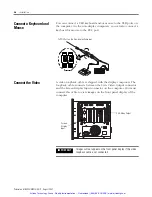
Page 27: ...h the display computers The loopback cable connects between the VGA Video Output connector and the Screen Display Input connector on the computer You must connect this cable to view images on the front panel display of the computer To PS 2 Port on the Non display Computer IMPORTANT Images will not appear on the front panel display if the video loopback cable is not connected Screen Display Input V...

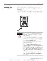
Page 28: ...o Earth ground will satisfy this requirement Otherwise connect your computer to Earth ground using a 1 3 mm2 16 AWG or larger external wire The ground wire should have green insulation with a yellow stripe for easy identification The power source must have its own disconnect Do not connect the computer to a supply that is connected to the main electrical disconnect To prevent problems resulting fr...

Page 29: ...erminal block screw 3 Apply 24V dc power to the computer ATTENTION Use a Class 2 SELV safety extralow voltage isolated and ungrounded power supply as input power to the computer This power source provides protection so that under normal and single fault conditions the voltage between the conductors and Functional Earth Protective Earth does not exceed a safe value V dc positive V dc negative Gnd g...

Page 30: ...net communication do not subject the computer or cables to extreme radiated or conducted high frequency noise Proper cable routing and power conditioning is required to be sure of reliable Ethernet communication in industrial environments Rockwell Automation recommends that you route all Ethernet cabling through dedicated metal conduits Installing ferrite bead filters at the cable ends may also im...

Page 31: ...Publication 6180W UM001H EN P August 2007 30 Installation Artisan Technology Group Quality Instrumentation Guaranteed 888 88 SOURCE www artisantg com ...

Page 32: ...t Windows operating system Do not operate the computer with the covers removed An electrical shock hazard exists Removing the covers will disrupt air flow and may result in overheating All covers are required to maintain EMI shield Operator Access Operator access is limited to the front panel of the workstation This includes the display keypad and touchscreen Access to components behind the panel ...

Page 33: ...here is no need to alter the switch settings Keypad operation is controlled by the switches as shown in the table Video Loopback Cable All 1200W workstations and 1500W series A workstations require that you install the video loopback cable for proper operation Make sure the cable is connected between the VGA video output connector and the screen display input connector SW1 SW2 Keypad Encoding 0 0 ...

Page 34: ...system usually selects the best device driver settings However to be sure of fully optimized performance by manually installing the device drivers included with your system Refer to the Readme files on the supplied accessory CD for details on the latest device drivers and installation procedures Universal Serial Bus USB Ports The Universal Serial Bus USB is an external bus standard that supports d...

Page 35: ...Publication 6180W UM001H EN P August 2007 34 Operation Artisan Technology Group Quality Instrumentation Guaranteed 888 88 SOURCE www artisantg com ...

Page 36: ...versaview Safety Precautions The computers contain line voltages Disconnect all power to the computer before you install or remove system components Electrostatic Discharge ESD ATTENTION Disconnect all power from the computer before removing components Failure to disconnect power could result in severe electrical shock or damage to the computer ATTENTION Electrostatic discharge ESD can damage the ...

Page 37: ...ollow these steps to remove the top and bottom covers 1 Disconnect power from the computer 2 Remove the 7 screws from the top cover or the 11 screws from the bottom cover 3 Lift the cover from the chassis ATTENTION Failure to follow proper safety precautions could result in severe electrical shock and or damage to the computer Artisan Technology Group Quality Instrumentation Guaranteed 888 88 SOUR...

Page 38: ...ge the brackets at the base and tighten the thumb screws Install or Remove Add in Cards You can install ISA and PCI compatible cards ATTENTION Failure to follow proper safety precautions could result in severe electrical shock and or damage to the computer ATTENTION Add in cards are sensitive to ESD and require careful handling Hold cards only by the edges Do not touch connectors components or cir...

Page 39: ...sis and then lifting them out of the bracket latch at the other end 4 Remove the screw securing the slot cover to the chassis at the selected slot location and remove the slot cover 5 Remove the add in card from its anti static packaging 6 Hold the card by the edges and firmly press the board into the slot on the backplane 7 Confirm that the card is fully seated in the backplane connector 8 Attach...

Page 40: ...e an add in card 1 Disconnect power from the computer 2 Remove the cover 3 Remove the hold down bracket by removing the screw securing it to the chassis 4 Lift the hold down bracket out of the bracket latch at the other end 5 Remove the screw securing the add in card s orb to the chassis 6 Pull the add in card free of the slot Store the card in an anti static wrapper 7 Install a slot cover over th...

Page 41: ...k drive Do not touch internal components unnecessarily Always handle the hard disk drive by its metal frame Store the hard disk drive in an anti static bag when it is not installed Never remove or install a hard disk drive with the power on ATTENTION Failure to follow proper safety precautions could result in severe electrical shock and or damage to the computer ATTENTION Mechanical shock can dama...

Page 42: ... mounting bracket to the drive 7 Remove the four screws that attach the anti shock brackets to the disk drive TIP The 1200W drive assembly includes the hard disk drive the floppy drive and the CD DVD drive You access the drive assembly through the bottom cover Four screws fasten the drive assembly to the chassis as shown in the 1200W Drive Assembly illustration After removing the 1200W drive assem...

Page 43: ... Non display Hard Disk Drive 1200W Drive Assembly Hard Disk Drive Anti Shock Brackets Mounting Bracket M3 6 32 6 32 1200W computer shown upside down Hard Disk Drive Floppy Drive CD DVD Drive Artisan Technology Group Quality Instrumentation Guaranteed 888 88 SOURCE www artisantg com ...

Page 44: ...vibration 5 Fasten the hard disk drive assembly to the chassis with two M3 screws 6 Reinstall the back cover Replace the Floppy Drive Follow these precautions when working with the floppy drive Do not touch internal components Always handle the floppy drive by its metal frame Store the floppy drive in an anti static bag when it is not installed Never disconnect or install a floppy drive with the p...

Page 45: ... the power supply to access both sides of the floppy drive to disengage lock points 6 Remove the six screws that secure the floppy drive to the drive cage 7 Slide the floppy drive out the front of the cage TIP For the 1200W remove the drive assembly as described under Replace the Hard Disk Drive You can then remove the floppy drive similar to the 1500W and non display workstations IMPORTANT Note t...

Page 46: ... to the floppy drive bracket with six screws 3 Reinsert the drive cage into the chassis making sure to engage lock points 4 Fasten the drive cage with the two screws on the outside of the chassis next to the new floppy drive 5 Connect the flat cable and power cable to the floppy drive 6 Reinstall the back cover Artisan Technology Group Quality Instrumentation Guaranteed 888 88 SOURCE www artisantg...

Page 47: ... back cover 3 Disconnect the power supply audio cable and ribbon cable from the drive ATTENTION Failure to follow proper safety precautions could result in severe electrical shock and or damage to the computer ATTENTION Mechanical shock can damage a CD ROM or DVD ROM drive Do not drop or bump the drive TIP For the 1200W remove the drive assembly as described under Replace the Hard Disk Drive You c...

Page 48: ... of the chassis 5 Lift the drive assembly out of the chassis 6 Slide the drive cage toward the power supply disengage lock points to access both sides of the drive 7 Remove the eight screws that fasten the drive to the drive cage 8 Slide the drive out the front of the cage Drive Cage Lock Point Artisan Technology Group Quality Instrumentation Guaranteed 888 88 SOURCE www artisantg com ...

Page 49: ...gle or double sided 3 3V Dual In Line Memory Module DIMM For memory replacement or expansion use the Allen Bradley 512 MB DIMM memory module catalog number 6189V DIMM512 Guidelines for Replacing Memory Always handle the memory cards by the ends not by the memory module contacts Store memory in a sealed anti static bag when it is not installed Never install or remove memory with the power turned on...

Page 50: ... retaining latches 5 To install a new DIMM hold the module by the edges as you remove it from its anti static package 6 Position the DIMM so that the small notches in the bottom edge of the DIMM align with the notches in the DIMM socket on the CPU card The retaining latches must be fully disengaged or open when you install a DIMM 7 Press down firmly and uniformly on the DIMM to seat it in the sock...

Page 51: ...Publication 6180W UM001H EN P August 2007 50 Replace System Components Artisan Technology Group Quality Instrumentation Guaranteed 888 88 SOURCE www artisantg com ...

Page 52: ...itor 6 Connect power to the computer When power is applied check the Power On Self Test POST If a nonfatal failure occurs POST emits beep codes that indicate errors in hardware software and firmware If a display monitor is attached POST can show a related error message However if a fatal error is detected the startup process is terminated 7 If the system restarts isolate the problem by connecting ...

Page 53: ...le as five minutes or as long as eight hours depending on the problem After the diagnostic utility has run you can generate a report for analysis by a technical support representative expediting any necessary repair process The diagnostic utility and documentation are on the VersaView Support CD that is shipped with your computer To run the diagnostic utility insert the Support CD into the compute...

Page 54: ...Problem After Start up If you are running a software package reinstall the software If the problem is intermittent you may have a loose connection Check all connections including any ISA PCI cards Check that the memory module is fully installed Does your system have a computer virus Run anti virus software Select Load Optimal Default in the CMOS setup procedure This will restore the BIOS settings ...

Page 55: ...upt you may need to reserve that interrupt in the CMOS setup PCI PnP menu Problems with the Display Are the display contrast and brightness controls properly adjusted Refer to the operating system containing the video driver for setup functions Is the monitor compatible with the selected video mode If you are using the integrated display try to correct the problem by pressing the Auto Adjust butto...

Page 56: ...ter at the power source 2 Clean the display with a mild soap or detergent by using a clean sponge or a soft cloth 3 Dry the display with a chamois or moist cellulose sponge to avoid water spots ATTENTION Use of abrasive cleansers or solvents may damage the display window Do not scrub or use brushes ATTENTION If the computer has a touchscreen be aware that it is possible for screen objects to activ...

Page 57: ...anasonic battery part number CR2032 or equivalent The battery life depends on the amount of on time time computer is powered on per week ATTENTION Make sure the isopropyl alcohol does not come in contact with the equipment labels Alcohol may cause the label printing to smear WARNING To avoid the danger of explosion only replace the battery with part number CR2032 or a recommended equivalent Dispos...

Page 58: ...r location you must first uninstall the product and place it in its original packing material ATTENTION The backlight assembly in this unit contains mercury At the end of its life this equipment should be collected separately from any unsorted municipal waste ATTENTION Do not ship or transport the product when it is installed in a machine panel or rack Doing so may cause damage to the product You ...

Page 59: ...Publication 6180W UM001H EN P August 2007 58 Maintenance Artisan Technology Group Quality Instrumentation Guaranteed 888 88 SOURCE www artisantg com ...

Page 60: ... Line frequency ac 47 63 Hz Power consumption ac 160 VA 1 6 A at 100V rms 0 67 A at 240V rms Power dissipation ac 160 W Input voltage dc 19 32V dc Power consumption dc 180 W 7 5 A at 24V dc Inrush current at 24V 20 A peak 5 ms Mechanical Weight 1200W 1500W Non display workstations 17 kg 37 4 lb 18 5 kg 40 8 lb 16 5 kg 36 4 lb Dimensions overall HxWxD approx 1200W 1500W Non display workstations 311...

Page 61: ...p p 10 57 Hz 2 g peak 57 500 Hz Shock operating 15 g 1 2 sine 11 ms Shock nonoperating 30 g 1 2 sine 11 ms Enclosure ratings panel mounted NEMA Type 4 12 IEC IP66 Certifications 1 1 See http ab com for declarations of conformity certificates and other certification details Attribute Value c UL us UL 60950 recognized component c UL 950 recognized component or UL c UL listed when marked CE Marked fo...

Page 62: ...the accessory cd For Additional Information For more information on setting up or operating a touchscreen or for future driver upgrades refer to http www ab com Resistive Touchscreen Technology Resistive touchscreens are activated when you apply pressure to the touchscreen with your finger You can operate a resistive touchscreen while wearing gloves TIP If it becomes necessary to reinstall the tou...

Page 63: ...ted Follow these steps to recalibrate the touchscreen 1 Run the touchscreen configuration utility through the PROGRAMS menu of the operating system 2 Start the calibration routine offered within the utility 3 Follow the calibration instructions given on the computer screen Artisan Technology Group Quality Instrumentation Guaranteed 888 88 SOURCE www artisantg com ...

Page 64: ...a display monitor keyboard and external USB floppy drive to the VersaView computer 2 On any computer connected to the Internet and containing a floppy disk go to the website http www ab com versaview 3 Click Support Resources Drivers 4 Click the link matching your computer s description and navigate to your specific product 5 On your computer s VersaView Downloads page click the link for the Syste...

Page 65: ...Publication 6180W UM001H EN P August 2007 64 Upgrade to a New BIOS Artisan Technology Group Quality Instrumentation Guaranteed 888 88 SOURCE www artisantg com ...

Page 66: ...D ROM DVD ROM drive 46 clearances 20 connect keyboard 23 connect power 27 considerations 19 environment and enclosure 18 floppy drive 43 hard disk drive 40 memory modules 48 mounting procedure 21 mouse or keyboard 26 panel mounting 19 panel mounting guidelines 21 product dimensions 24 required tools 19 K keyboard or mouse connection 26 M maintenance battery 56 clean display 55 fan filter 57 memory...

Page 67: ...r software 61 serial port 61 type 61 troubleshooting check lists 53 diagnostic utility 52 distorted or incorrect characters 54 problem after start up 53 problem during start up 53 problem running software 54 problem with add in card 54 procedure 51 U USB installing or using 33 V video loopback cable 32 Artisan Technology Group Quality Instrumentation Guaranteed 888 88 SOURCE www artisantg com ...

Page 68: ...Artisan Technology Group Quality Instrumentation Guaranteed 888 88 SOURCE www artisantg com ...

Page 69: ...tance If you experience a problem within the first 24 hours of installation please review the information that s contained in this manual You can also contact a special Customer Support number for initial help in getting your product up and running New Product Satisfaction Return Rockwell Automation tests all of its products to ensure that they are fully operational when shipped from the manufactu...

Page 70: ...l service in house repair center WE BUY USED EQUIPMENT Sell your excess underutilized and idle used equipment We also offer credit for buy backs and trade ins www artisantg com WeBuyEquipment REMOTE INSPECTION Remotely inspect equipment before purchasing with our interactive website at www instraview com LOOKING FOR MORE INFORMATION Visit us on the web at www artisantg com for more information on ...

Reviews: