background image

3-42

Programming and Parameters

PowerFlex 40 Adjustable Frequency AC Drive FRN 1.xx - 7.xx User Manual
Publication 22B-UM001I-EN-E

Advanced Program Group

 (continued)

A150 [Stp Logic Time 0]
A151 [Stp Logic Time 1]
A152 [Stp Logic Time 2]
A153 [Stp Logic Time 3]
A154 [Stp Logic Time 4]
A155 [Stp Logic Time 5]
A156 [Stp Logic Time 6]
A157 [Stp Logic Time 7]

Related Parameter(s): 

P038

A055

A058

A061

,

A070

-

A077

A140

-

A147

Sets the time to remain in each step if the corresponding StpLogic command word is set to “Step after 
Time”.

Values

Default:

30.0 Secs

Min/Max:

0.0/999.9 Secs

Display:

0.1 Secs

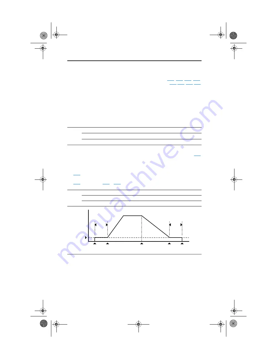
A160 [EM Brk Off Delay]

Related Parameter(s): 

P037

Sets the time the drive remains at minimum frequency before the relay or an opto output is energized 
and the drive ramps to the commanded frequency.
The relay or opto output is typically connected to a user-supplied electromechanical brake coil relay.
Set 

P037

 [Stop Mode] to 8 “Ramp+EM B,CF” or 9 “Ramp+EM Brk” to enable the electromechanical 

brake option.
Set 

A055

 [Relay Out Sel], 

A058

 or 

A061

 [Opto Outx Sel] to 22 “EM Brk Cntrl” to control brake 

operation.
Values

Default:

2.00 Secs

Min/Max:

0.01/10.00 Secs

Display:

0.01 Secs

Frequency

Time

Minimum Freq

A160 [EM Brk Off Delay]

A161 [EM Brk On Delay]

Stop

Commanded

Start

Commanded

EM Brk

De-Energized (On)

Drive Stops

EM Brk
Energized (Off)

Ramp Accel

Ramp Decel

22B-UM001.book  Page 42  Tuesday, May 30, 2017  5:22 PM

Summary of Contents for Allen-Bradley PowerFlex 40 22B-B8P0N104

Page 1: ...Adjustable Frequency AC Drive FRN 1 xx 7 xx User Manual www abpowerflex com 22B UM001 book Page 1 Tuesday May 30 2017 5 22 PM ...

Page 2: ...d diagrams No patent liability is assumed by Rockwell Automation Inc with respect to use of information circuits equipment or software described in this manual Reproduction of the contents of this manual in whole or in part without written permission of Rockwell Automation Inc is prohibited Throughout this manual when necessary we use notes to make you aware of safety considerations Important Iden...

Page 3: ...n and new footnotes added 1 9 A 2 Drive Fuse Circuit Breaker Ratings topic updated A 1 Electronic Motor Overload Protection description updated A 4 Description of New or Updated Information Page s Description of A056 revised 3 17 Description of A059 A062 revised 3 19 Fault description for F3 revised 4 3 A table row for electrical specifications added A 4 Graphic for the Network Wiring section revi...

Page 4: ...arameter Number Description Page Relay Out Sel A055 Function of option 20 ParamControl changed Option 24 MsgControl added 3 16 Relay Out Sel A058 A061 Function of option 20 ParamControl changed Option 24 MsgControl added 3 18 Parameter Number Description Page Control Source d012 Options 7 and 8 added 3 5 Start Source P036 Description revised for option 6 3 10 Relay Out Sel A055 Description revised...

Page 5: ...ons 1 14 Start and Speed Reference Control 1 23 EMC Instructions 1 25 Chapter 2 Start Up Prepare For Drive Start Up 2 1 Integral Keypad 2 4 Viewing and Editing Parameters 2 5 Remote HIM Menu Structure 2 6 Chapter 3 Programming and Parameters About Parameters 3 1 Parameter Organization 3 2 Display Group 3 3 Basic Program Group 3 9 Advanced Program Group 3 14 Parameter Cross Reference by Name 3 45 C...

Page 6: ...Additional Information C 7 Appendix D RJ45 DSI Splitter Cable Connectivity Guidelines D 1 DSI Cable Accessories D 2 Connecting One Temporary Peripheral D 3 Connecting One Temporary Peripheral and One Permanent Peripheral D 3 Connecting Two Permanent Peripherals D 4 Connecting an RS 485 Network D 4 Appendix E StepLogic Basic Logic and Timer Counter Functions StepLogic Using Timed Steps E 2 StepLogi...

Page 7: ...ormation For information on See page Who Should Use this Manual P 1 Reference Materials P 1 Manual Conventions P 2 Drive Frame Sizes P 2 General Precautions P 3 Catalog Number Explanation P 4 Who Should Use this Manual Reference Materials Title Publication Available Online at Wiring and Grounding Guidelines for Pulse Width Modulated PWM AC Drives DRIVES IN001 www rockwellautomation com literature ...

Page 8: ...re grouped into frame sizes to simplify spare parts ordering dimensioning etc A cross reference of drive catalog numbers and their respective frame sizes is provided in Appendix B Manual Conventions P031 Motor NP Volts Name Number Group d Display Group P Basic Program Group A Advanced Program Group Word Meaning Can Possible able to do something Cannot Not possible not able to do something May Perm...

Page 9: ...dures are not followed If you are not familiar with static control procedures reference A B publication 8000 4 5 2 Guarding Against Electrostatic Damage or any other applicable ESD protection handbook ATTENTION An incorrectly applied or installed drive can result in component damage or a reduction in product life Wiring or application errors such as undersizing the motor incorrect or inadequate AC...

Page 10: ... 5 0 0 75 1 0 6P0 6 0 1 1 1 5 Code Rating 0 Not Filtered 1 Filtered Output Current 380 480V 50 60 Hz Input Code Amps kW HP 1P4 1 4 0 4 0 5 2P3 2 3 0 75 1 0 4P0 4 0 1 5 2 0 6P0 6 0 2 2 3 0 010 10 5 4 0 5 0 012 12 5 5 7 5 017 17 7 5 10 024 24 11 15 Code 22B PowerFlex 40 Additional accessories options and adapters are available See Appendix B for details Output Current 500 600V 50 60 Hz Input Code Am...

Page 11: ... release For information on See page For information on See page Opening the Cover 1 1 Fuses and Circuit Breakers 1 8 Mounting Considerations 1 3 Power Wiring 1 10 AC Supply Source Considerations 1 5 I O Wiring Recommendations 1 14 General Grounding Requirements 1 7 EMC Instructions 1 25 ATTENTION The following information is merely a guide for proper installation Rockwell Automation Inc cannot as...

Page 12: ...rnating pattern ATTENTION To avoid an electric shock hazard ensure isolation of mains supply from line inputs R S T L1 L2 L3 and wait three minutes for capacitors to discharge before removing the external cover Once the cover is removed verify that the voltage on the bus capacitors has discharged before performing any work on the drive Measure the DC bus voltage at the DC and DC terminals on the P...

Page 13: ... 96 N m 14 17 lb in 35 mm C M5 10 24 2 45 2 94 N m 22 26 lb in B IP66 Type 4X M6 12 24 3 95 4 75 N m 35 42 lb in Ambient Temperature Enclosure Rating Minimum Mounting Clearances Minimum Maximum 10 C 14 F 40 C 104 F IP20 NEMA UL Type Open Use Mounting Option A IP66 NEMA UL Type 4X Use Mounting Option A IP30 NEMA UL Type 1 1 1 Rating requires installation of the PowerFlex 40 IP30 NEMA UL Type 1 opti...

Page 14: ...e Install the panel to prevent debris from falling through the vents of the drive housing during installation Remove the panel for IP20 NEMA UL Type Open applications Storage Store within an ambient temperature range of 40 to 85 C Store within a relative humidity range of 0 to 95 non condensing Do not expose to a corrosive atmosphere 22B UM001 book Page 4 Tuesday May 30 2017 5 22 PM ...

Page 15: ...in the Figures 1 1 and 1 2 1 Turn the screw counterclockwise to loosen 2 Pull the jumper completely out of the drive chassis 3 Tighten the screw to keep it in place Figure 1 1 Jumper Location Typical Figure 1 2 Phase to Ground MOV Removal AC Supply Source Considerations ATTENTION PowerFlex 40 drives contain protective MOVs that are referenced to ground These devices must be disconnected if the dri...

Page 16: ... 7 5 15 HP drives only 2 Refer to Appendix B for accessory ordering information Greater than 120 kVA supply transformer Line has power factor correction capacitors Install Line Reactor or Isolation Transformer Line has frequent power interruptions Line has intermittent noise spikes in excess of 6000V lightning Phase to ground voltage exceeds 125 of normal line to line voltage Remove MOV jumper to ...

Page 17: ...ound rod or bus bar Grounding points must comply with national and local industrial safety regulations and or electrical codes Motor Ground The motor ground must be connected to one of the ground terminals on the drive Shield Termination SHLD Either of the safety ground terminals located on the power terminal block provides a grounding point for the motor cable shield The motor cable shield connec...

Page 18: ...ct should be installed with either input fuses or an input circuit breaker National and local industrial safety regulations and or electrical codes may determine additional requirements for these installations Fusing The PowerFlex 40 has been UL tested and approved for use with input fuses The ratings in the table that follows are the minimum recommended values for use with each drive rating The d...

Page 19: ...E B40 140M C2E B63 140M C2E C10 140M C2E C16 140M D8E C20 140M D8E C20 140M F8E C32 100 C07 100 C07 100 C09 100 C09 100 C23 100 C23 100 C23 100 C43 1655 1655 1655 1655 1655 2069 2069 2069 600V AC 3 Phase 0 75 1 0 1 5 2 0 2 2 3 0 4 0 5 0 5 5 7 5 7 5 10 0 11 15 6 6 10 15 20 25 40 140M C2E B25 140M C2E B40 140M D8E B63 140M D8E C10 140M D8E C16 140M D8E C16 140M F8E C25 100 C09 100 C09 100 C09 100 C0...

Page 20: ...hosen must have a minimum insulation thickness of 15 mils and should not have large variations in insulation concentricity Shielded Armored Cable Shielded cable contains all of the general benefits of multi conductor cable with the added benefit of a copper braided shield that can contain much of the noise generated by a typical AC Drive Strong consideration for shielded cable should be given in i...

Page 21: ...available but the selection of these types may limit the allowable cable length Particularly some of the newer cables twist 4 conductors of THHN wire and wrap them tightly with a foil shield This construction can greatly increase the cable charging current required and reduce the overall drive performance Unless specified in the individual distance tables as tested with the drive these cables are ...

Page 22: ...s Output Disconnect The drive is intended to be commanded by control input signals that will start and stop the motor A device that routinely disconnects then reapplies output power to the motor for the purpose of starting and stopping the motor should not be used If it is necessary to disconnect power to the motor with the drive outputting power an auxiliary contact should be used to simultaneous...

Page 23: ...e C Frame drive is shipped with a jumper between Terminals P2 and P1 Remove this jumper only when a DC Bus Inductor will be connected Drive will not power up without a jumper or inductor connected DC DC DC Bus Connection BR BR Dynamic Brake Resistor Connection Safety Ground PE 1 Important Terminal screws may become loose during shipment Ensure that all terminal screws are tightened to the recommen...

Page 24: ...other device that routinely disconnects and reapplies the AC line to the drive to start and stop the motor can cause drive hardware damage The drive is designed to use control input signals that will start and stop the motor If used the input device must not exceed one operation per minute or drive damage can occur ATTENTION The drive start stop control circuitry includes solid state components If...

Page 25: ... I O terminal block Common must be connected to ground terminal protective earth If using the RS485 DSI port I O Terminal 16 should also be connected to ground terminal protective earth Wire Type s 2 Description Minimum Insulation Rating Belden 8760 9460 or equiv 0 8 mm2 18AWG twisted pair 100 shield with drain 1 1 If the wires are short and contained within a cabinet which has no sensitive circui...

Page 26: ...e output 4 When the ENBL enable jumper is removed I O Terminal 01 will always act as a hardware enable causing a coast to stop without software interpretation 04 05 06 07 01 02 03 08 09 11 12 13 14 15 16 17 18 19 Digital Common Digital Input 1 Digital Input 2 Digital Input 3 Stop 1 4 Start Run FWD 2 Direction Run REV Digital Input 4 Opto Common R1 R2 R3 Relay N O Relay Common Relay N C 24V DC 10V ...

Page 27: ...Electronically isolated with opto outputs from analog I O and digital inputs 11 24V DC Referenced to Digital Common Drive supplied power for digital inputs Maximum output current is 100mA 12 10V DC Referenced to Analog Common Drive supplied power for 0 10V external potentiometer Maximum output current is 15mA P038 13 10V In 2 Not Active For external 0 10V unipolar or 10V bipolar input supply input...

Page 28: ...V Bipolar Enbl 1 Bi Polar In Unipolar Voltage P038 Speed Reference 2 0 10V Input Unipolar Current P038 Speed Reference 3 4 20mA Input Analog Input PTC For Drive Fault Wire the PTC and External Resistor typically matched to the PTC Hot Resistance to I O Terminals 12 13 14 Wire R2 R3 Relay Output SRC to I O Terminals 5 11 A051 Digital In1 Sel 3 Aux Fault A055 Relay Out Sel 10 Above Anlg V A056 Relay...

Page 29: ...Reversing Internal Supply SNK 2 Wire SRC Control Run FWD Run REV P036 Start Source 2 3 or 4 Input must be active for the drive to run When input is opened the drive will stop as specified by P037 Stop Mode If both Run Forward and Run Reverse inputs are closed at the same time an undetermined state could occur Internal Supply SRC External Supply SRC Input Output Connection Example 11 01 02 Stop Run...

Page 30: ...Reversing Internal Supply SNK 3 Wire SRC Control Reversing P036 Start Source 1 A momentary input will start the drive A stop input to I O Terminal 01 will stop the drive as specified by P037 Stop Mode I O Terminal 03 determines direction Internal Supply SRC External Supply SRC Input Output Connection Example Stop Run Forward Stop Run Reverse 01 02 03 04 11 01 02 Stop Start 01 02 04 24V Common Stop...

Page 31: ...y install a recovery diode parallel to the relay as shown to prevent damage to the output Opto Output 1 Analog Output A065 Analog Out Sel determines analog output type and drive conditions 0 10V 1k ohm minimum 0 20mA 4 20mA 525 ohm maximum A065 Analog Out Sel 0 through 14 The Analog Output Select DIP Switch must be set to match the analog output signal mode set in A065 Analog Out Sel Input Output ...

Page 32: ...ain of I O Terminal 04 should be connected Multiple Analog Connections When connecting a single potentiometer to multiple drives it is important to connect I O Terminal 14 common together for all drives I O Terminal 14 common and I O Terminal 13 potentiometer wiper should be daisy chained to each drive All drives must be powered up for the analog signal to be read correctly Customer Inputs Optiona...

Page 33: ...eed and Direction commands come from Integral Keypad Comm Select Input Enabled and Active Digital Inx Sel 6 No Yes Start Speed and Direction commands come from RS485 DSI port 0 10V Override Enabled and Active Digital Inx Sel 13 No Yes Speed commands come from 0 10V Start and Direction follows P036 Start Source or Bi Polar input when enabled Speed commands come from 4 20mA Start and Direction follo...

Page 34: ...ed when RS485 DSI port is active Input is programmed as Accel 2 Decel 2 A051 A052 A053 or A054 1 No Yes A067 Accel Time 2 A068 Decel Time 2 is active when input is active Speed is controlled by Preset Freq x No Yes P039 Accel Time 1 P040 Decel Time 1 A067 Accel Time 2 A068 Decel Time 2 determined by the active Preset Frequency See A070 A077 Preset Freq 0 7 Either P039 Accel Time 1 P040 Decel Time ...

Page 35: ... thermal and energy EMC Directive 2014 30 EU EN61800 3 Adjustable speed electrical power drive systems Part 3 EMC product standard including specific test methods General Notes If the plastic top panel is removed or the optional conduit box is not installed the drive must be installed in an enclosure with side openings less than 12 5 mm 0 5 in and top openings less than 1 0 mm 0 04 in to maintain ...

Page 36: ...5011 Class A 3 Equivalent to EN55011 Class B Figure 1 6 Connections and Grounding 1 First Environment Unrestricted Distribution installations require a shielded enclosure Keep wire length as short as possible between the enclosure entry point and the EMI filter 2 Integral EMI filters are available on 240V 1 Phase drives Filter Type EN61800 3 First Environment Restricted Distribution or Second Envi...

Page 37: ...es and 0 37 kW 0 5 HP 240V 1 Phase drives are suitable for installation on a private low voltage power network Installations on a public low voltage power network may require additional external harmonic mitigation Other drive ratings meet the current harmonic requirements of EN61000 3 2 without additional external mitigation 22B UM001 book Page 27 Tuesday May 30 2017 5 22 PM ...

Page 38: ...1 28 Installation Wiring PowerFlex 40 Adjustable Frequency AC Drive FRN 1 xx 7 xx User Manual Publication 22B UM001I EN E Notes 22B UM001 book Page 28 Tuesday May 30 2017 5 22 PM ...

Page 39: ...s 01 and 11 to allow starting from the keypad If the control scheme is changed to Sink SNK the jumper must be removed from I O Terminals 01 and 11 and installed between I O Terminals 01 and 04 5 Verify that the Stop input is present or the drive will not start Important If I O Terminal 01 is used as a stop input the jumper between I O Terminals 01 and 11 must be removed ATTENTION Power must be app...

Page 40: ...ol speed directly from the integral keypad Important To disable reverse operation see A095 Reverse Disable Changing the Speed Reference of an IP66 NEMA UL Type 4X rated drive When a Display Group parameter for example d001 Output Freq is displayed and P038 Speed Ref is set to A069 Internal Freq you can change the internal frequency using the Up Arrow and Down Arrow keys When the internal frequency...

Page 41: ...o enter the program mode see Viewing and Editing Parameters on page 2 5 Note The default value of A069 Internal Freq is 0 Hz For IP20 rated PowerFlex 40 drives the default value of this parameter is 60 Hz Variable Torque Fan Pump Applications For improved motor tuning performance when using a premium efficient motor on a variable torque load set A084 Boost Select to option 2 35 0 VT 22B UM001 book...

Page 42: ...Select a digit when viewing parameter value Up Arrow Down Arrow Scroll through groups and parameters Increase decrease the value of a flashing digit Used to adjust internal frequency of IP66 NEMA UL Type 4X rated drives only when a Display Group parameter is shown and P038 Speed Reference is set to internal frequency A069 Internal Freq Enter Advance one step in programming menu Save a change to a ...

Page 43: ... the Up Arrow or Down Arrow to scroll through the parameters that are in the group 7 Press Enter or Sel to view the value of a parameter If you do not want to edit the value press Esc to return to the parameter number 8 Press Enter or Sel to enter program mode to edit the parameter value The right digit will flash and the Program LED will illuminate if the parameter can be edited 9 Press the Up Ar...

Page 44: ...n Press Press Press to move between menu items Press to move between main menu tabs to select a tab or menu item to move 1 level back in the menu structure Memory Storage HIM CopyCat Device HIM Device HIM Delete File Function File Name File Name File Name File Name File Name PowerFlex 40 Connected DSI Devices Device Select Parameters Device Cat No Device Name Series Firmware Group Name Parameter N...

Page 45: ...iles stored in permanent nonvolatile HIM memory HIM Setup Menu The HIM and drive have features that you can customize Option Description Faults View fault queue or fault information clear faults or clear fault queue Device Status View status information about the drive or peripheral Device Version View the firmware version and hardware series of components Option Description HIM Copycat Device HIM...

Page 46: ...2 8 Start Up PowerFlex 40 Adjustable Frequency AC Drive FRN 1 xx 7 xx User Manual Publication 22B UM001I EN E Notes 22B UM001 book Page 8 Tuesday May 30 2017 5 22 PM ...

Page 47: ...low a selection from 2 or more items Each item is represented by a number Numeric Parameters These parameters have a single numerical value i e 0 1 Volts Bit Parameters Bit parameters have four individual bits associated with features or conditions If the bit is 0 the feature is off or the condition is false If the bit is 1 the feature is on or the condition is true Some parameters are marked as f...

Page 48: ...ef A129 PID Trim Hi A130 PID Trim Lo A131 PID Ref Sel A132 PID Feedback Sel A133 PID Prop Gain A134 PID Integ Time A135 PID Diff Rate A136 PID Setpoint A137 PID Deadband A138 PID Preload A139 Stp Logic 0 A140 Stp Logic 1 A141 Stp Logic 2 A142 Stp Logic 3 A143 Stp Logic 4 A144 Stp Logic 5 A145 Stp Logic 6 A146 Stp Logic 7 A147 Stp Logic Time 0 A150 Stp Logic Time 1 A151 Stp Logic Time 2 A152 Stp Lo...

Page 49: ...g Important The frequency command can come from a number of sources Refer to Start and Speed Reference Control on page 1 23 for details Values Default Read Only Min Max 0 0 P035 Maximum Freq Display 0 1 Hz d003 Output Current The output current present at T1 T2 T3 U V W Values Default Read Only Min Max 0 00 Drive Rated Amps 2 Display 0 01 Amps d004 Output Voltage Related Parameter s P031 A084 A088...

Page 50: ...de d008 Fault 2 Code d009 Fault 3 Code A code that represents a drive fault The codes will appear in these parameters in the order they occur d007 Fault 1 Code the most recent fault Repetitive faults will only be recorded once Refer to Chapter 4 for fault code descriptions Values Default Read Only Min Max F2 F122 Display F1 d010 Process Display Related Parameter s d001 A099 32 bit parameter The ou...

Page 51: ... Freq 2 0 10V Input Remote Potentiometer 3 4 20mA Input 4 A070 A077 Preset Freq x A051 A053 Digital Inx Sel must be set to 4 5 RS485 DSI Port 6 StepLogic Control Parameters A140 A147 7 Anlg In Mult 8 PID 9 Jog Freq Reserved Digit 2 Reserved Digit 3 d013 Contrl In Status Related Parameter s d002 P034 P035 Status of the control terminal block control inputs Important Actual control commands may come...

Page 52: ... 07 Bit 2 Digital In4 Sel I O Terminal 08 Bit 3 d015 Comm Status Related Parameter s A103 A107 Status of the communications ports Values Default Read Only Min Max 0 1 Display 1 1 Condition True 0 Condition False Receiving Data Bit 0 Transmitting Data Bit 1 RS485 DSI Based Option Connected Bit 2 Allen Bradley devices only Communication Error Occurred Bit 3 d016 Control SW Ver Main Control Board sof...

Page 53: ...20 Analog In 0 10V Related Parameter s A110 A111 The present value of the voltage at I O Terminal 13 100 0 10 volts Values Default Read Only Min Max 0 0 100 0 Display 0 1 d021 Analog In 4 20mA Related Parameter s A112 A113 The present value of the current at I O Terminal 15 0 0 4mA 100 0 20mA Values Default Read Only Min Max 0 0 100 0 Display 0 1 d022 Output Power Output power present at T1 T2 T3 ...

Page 54: ...0 9999 Display 1 d026 Timer Status 32 bit parameter The current value of the timer when timer is enabled Values Default Read Only Min Max 0 0 9999 Secs Display 0 1 Secs 32 d028 Stp Logic Status When P038 Speed Reference is set to 6 Stp Logic this parameter will display the current step of the StepLogic profile as defined by parameters A140 A147 Stp Logic x Values Default Read Only Min Max 0 7 Disp...

Page 55: ...Current Related Parameter s A055 A058 A061 A089 A090 A098 A114 A118 Set to the maximum allowable motor current The drive will fault on an F7 Motor Overload if the value of this parameter is exceeded by 150 for 60 seconds Values Default Based on Drive Rating Min Max 0 0 Drive Rated Amps 2 Display 0 1 Amps P034 Minimum Freq Related Parameter s d001 d002 d013 P035 A085 A086 A087 A110 A112 Sets the lo...

Page 56: ...ording to the value set in P037 Stop Mode 2 2 Wire I O Terminal 1 Stop coast to stop 3 2 W Lvl Sens Drive will restart after a Stop command when Stop is removed and Start is held active 4 2 W Hi Speed Important There is greater potential voltage on the output terminals when using this option Outputs are kept in a ready to run state The drive will respond to a Start command within 10 ms I O Termina...

Page 57: ...e ENBL enable jumper on the control board In this case the drive will always coast to a stop regardless of the settings of P036 Start Source and P037 Stop Mode Options 0 Ramp CF 1 Default Ramp to Stop Stop command clears active fault 1 Coast CF 1 Coast to Stop Stop command clears active fault 2 DC Brake CF 1 DC Injection Braking Stop Stop command clears active fault 3 DCBrkAuto CF 1 DC Injection B...

Page 58: ...ult Internal frequency command from A069 Internal Freq Must be set when using MOP function 2 0 10V Input External frequency command from the 0 10V or 10V analog input or remote potentiometer 3 4 20mA Input External frequency command from the 4 20mA analog input 4 Preset Freq External frequency command as defined by A070 A077 Preset Freq x when A051 A054 Digital Inx Sel are programmed as Preset Fre...

Page 59: ...s Stop drive before changing this parameter Resets all parameter values to factory defaults Options 0 Ready Idle Default 1 Factory Rset After the reset function is complete this parameter will set itself back to 0 Causes an F48 Params Defaulted fault P042 Voltage Class Stop drive before changing this parameter Sets the voltage class of 600V drives Options 2 Low Voltage 480V 3 High Voltage Default ...

Page 60: ... removed 4 Preset Freq A051 A052 Default Refer to A070 A077 Preset Freq x Important Digital Inputs have priority for frequency control when programmed as Preset Speed and are active Refer to the flowchart on page 1 23 for more information on speed reference control priority 5 Local A053 Default When active sets integral keypad as start source and potentiometer on the integral keypad as speed sourc...

Page 61: ...trol the relay or opto outputs 19 Counter In Starts the counter function May be used to control the relay or opto outputs 20 Reset Timer Clears the active timer 21 Reset Countr Clears the active counter 22 Rset Tim Cnt Clears the active timer and counter 23 Logic In1 Logic function input number 1 May be used to control the relay or opto outputs see parameters A055 A058 A061 Options 11 14 May be us...

Page 62: ... Relay Out Level must be entered in percent of drive rated output current 8 Above DCVolt Drive exceeds the DC bus voltage value set in A056 Relay Out Level Use A056 to set threshold 9 Retries Exst Value set in A092 Auto Rstrt Tries is exceeded 10 Above Anlg V Analog input voltage I O Terminal 13 exceeds the value set in A056 Relay Out Level DonotuseifA123 10VBipolarEnbl issetto1 Bi PolarIn This pa...

Page 63: ...EM Brk Cntrl EM brake is energized Program A160 EM Brk Off Delay and A161 EM Brk On Delay for desired action 23 Above Fcmd The current commanded frequency exceeds the value set in A056 Relay Out Level 24 MsgControl With FRN 4 01 and later this option enables the output to be controlled over network communications by writing to A056 Relay Out Level 0 Off 1 On A056 Relay Out Level Related Parameter ...

Page 64: ...r A062 to set threshold Important Value for A059 or A062 Opto Outx Level must be entered in percent of drive rated output current 8 Above DCVolt Drive exceeds the DC bus voltage value set in A059 or A062 Opto Outx Level Use A059 or A062 to set threshold 9 Retries Exst Value set in A092 Auto Rstrt Tries is exceeded 10 Above Anlg V Analog input voltage I O Terminal 13 exceeds the value set in A059 o...

Page 65: ...to Rstrt Tries in not enabled A Non resettable fault has occurred 22 EM Brk Cntrl EM brake is energized Program A160 EM Brk Off Delay and A161 EM Brk On Delay for desired action 23 Above Fcmd The current commanded frequency exceeds the value set in A059 or A062 Opto Outx Level 24 MsgControl With FRN 4 01 and later Enables the output to be controlled over the network communications by writing to A0...

Page 66: ...35 Hex FFFF 0 10V d019 5 OutFreq 0 20 0 20mA 0 mA 0 Hz P035 Maximum Freq 0 20mA d001 6 OutCurr 0 20 0 20mA 0 mA 0 Amps 200 Drive Rated Output Current 0 20mA d003 7 OutVolt 0 20 0 20mA 0 mA 0 Volts 120 Drive Rated Output Volts 0 20mA d004 8 OutPowr 0 20 0 20mA 0 mA 0 kW 200 Drive Rated Power 0 20mA d022 9 TstData 0 20 0 20mA 0 mA 0000 65535 Hex FFFF 0 20mA d019 10 OutFreq 4 20 4 20mA 4 mA 0 Hz P035...

Page 67: ...0 1 OutCurr 0 10 5V for 200 Drive Rated Output Current 90 8 OutPowr 0 20 18mA for 200 Drive Rated Power A067 Accel Time 2 Related Parameter s P039 A051 A054 A070 A077 A140 A147 When active sets the rate of acceleration for all speed increases except jog Refer to the flowchart on page 1 24 for details Values Default 20 0 Secs Min Max 0 0 600 0 Secs Display 0 1 Secs Maximum Freq Accel Time Accel Rat...

Page 68: ...q Related Parameter s P038 A162 Provides the frequency command to the drive when P038 Speed Reference is set to 1 Internal Freq When enabled this parameter will change the frequency command in real time using the integral keypad Up Arrow or Down Arrow when in program mode Important Once the desired command frequency is reached the Enter key must be pressed to store this value to EEPROM memory If t...

Page 69: ... 0 set P038 Speed Reference to option 4 Preset Freq 0 3 Input State of Digital In 1 I O Terminal 05 when A051 4 Input State of Digital In 2 I O Terminal 06 when A052 4 Input State of Digital In 3 I O Terminal 07 when A053 4 Frequency Source Accel Decel Parameter Used 2 0 0 0 A070 Preset Freq 0 Accel Time 1 Decel Time 1 1 0 0 A071 Preset Freq 1 Accel Time 1 Decel Time 1 0 1 0 A072 Preset Freq 2 Acc...

Page 70: ...uous Display 0 1 Secs A081 DC Brake Level Related Parameter s P037 A080 Defines the maximum DC brake current in amps applied to the motor when P037 Stop Mode is set to either Ramp or DC Brake Values Default Drive Rated Amps 0 05 Min Max 0 0 Drive Rated Amps 1 8 Display 0 1 Amps P037 DC Injection Braking Mode Volts Speed Voltage Time Stop Command Speed DC Brake Level DC Brake Time Volts Speed P037 ...

Page 71: ...rmal RA Res 5 Duty Cycle Refer to Table B C on page B 2 NoProtection 100 Duty Cycle x Duty Cycle Limited 3 99 of Duty Cycle ATTENTION A risk of fire exists if external braking resistors are not protected The external resistor package must be self protected from over temperature or the protective circuit shown in Figure B 9 on page B 13 or equivalent must be supplied A083 S Curve Sets the percentag...

Page 72: ...25 Torque Perf Mode 0 V Hz Drive may add additional voltage unless Option 5 is selected Options 0 Custom V Hz 1 30 0 VT Variable Torque Typical fan pump curves 2 35 0 VT 3 40 0 VT 4 45 0 VT 5 0 0 no IR Constant Torque 6 0 0 7 2 5 CT Default for 4 0 5 5 7 5 11 kW 5 0 7 5 10 15 HP Drives 8 5 0 CT Default 9 7 5 CT 10 10 0 CT 11 12 5 CT 12 15 0 CT 13 17 5 CT 14 20 0 CT P032 Motor NP Hertz P031 Motor N...

Page 73: ...A087 Break Frequency P032 Motor NP Hertz P035 Maximum Freq A085 Start Boost P031 Motor NP Volts A088 Maximum Voltage A086 Break Voltage A034 Minimum Freq A086 Break Voltage Related Parameter s P031 P032 P034 P035 A084 A085 A087 A088 A125 Sets the frequency where break voltage is applied when A084 Boost Select 0 Custom V Hz and A125 Torque Perf Mode 0 V Hz Values Default 25 0 Min Max 0 0 100 0 Disp...

Page 74: ...es Class 10 motor overload protection Settings 0 2 select the derating factor for the I2 t overload function Options 0 No Derate Default 1 Min Derate 2 Max Derate Min Derate 0 80 100 60 40 20 No Derate 0 80 100 60 40 20 of P033 Motor OL Curent Max Derate 0 80 100 60 40 20 0 200 175 150 125 100 75 50 25 0 200 175 150 125 100 75 50 25 0 200 175 150 125 100 75 50 25 A091 PWM Frequency Related Paramet...

Page 75: ...ocal national and international codes standards regulations or industry guidelines A093 Auto Rstrt Delay Related Parameter s A092 Sets the time between restart attempts when A092 Auto Rstrt Tries is set to a value other than zero Values Default 1 0 Secs Min Max 0 0 300 0 Secs Display 0 1 Secs A094 Start At PowerUp Stop drive before changing this parameter Enables disables a feature that allows a S...

Page 76: ...orrection options that may improve problems with motor instability Options 0 Disabled 1 Electrical Default Some drive motor combinations have inherent instabilities which are exhibited as non sinusodial motor currents This setting attempts to correct this condition 2 Mechanical Some motor load combinations have mechanical resonances which can be excited by the drive current regulator This setting ...

Page 77: ...ed Default 1 Locked A102 Testpoint Sel Related Parameter s d019 Used by Rockwell Automation field service personnel Values Default 400 Min Max 0 FFFF Display 1 Hex A103 Comm Data Rate Related Parameter s d015 Sets the serial port rate for the RS485 DSI port Important Power to drive must be cycled before any changes will affect drive operation Options 0 1200 1 2400 2 4800 3 9600 Default 4 19 2K 5 3...

Page 78: ...e will remain in communication loss before implementing the option selected in A105 Comm Loss Action Values Default 5 0 Secs Min Max 0 1 60 0 Secs Display 0 1 Secs A107 Comm Format Related Parameter s d015 Selects the protocol RTU only data bits 8 data bits only parity None Even Odd and stop bits 1 stop bit only used by the RS485 port on the drive Refer to Appendix C for details on using the drive...

Page 79: ...Values Default 0 0 Min Max 0 0 100 0 Display 0 1 0 P035 Maximum Freq P034 Minimum Freq A110 Anlg In 0 10V Lo A111 Anlg In 0 10V Hi 0 Speed Reference A111 Anlg In 0 10V Hi Related Parameter s d020 P035 P038 A122 A123 Sets the analog input level that corresponds to P035 Maximum Freq if a 0 10V input is used by P038 Speed Reference Analog inversion can be accomplished by setting this value smaller th...

Page 80: ...When set to a value other than zero d010 Process Display indicates the duration of the process Values Default 0 00 Min Max 0 00 99 99 Display 0 01 A116 Process Time Hi Related Parameter s d010 P035 Scales the time value when the drive is running at P035 Maximum Freq When set to a value other than zero d010 Process Display indicates the duration of the process Values Default 0 00 Min Max 0 00 99 99...

Page 81: ...119 Determines the bandwidth around A119 Skip Frequency A120 Skip Frequency Band is split applying 1 2 above and 1 2 below the actual skip frequency A setting of 0 0 disables this parameter Values Default 0 0 Hz Min Max 0 0 30 0 Hz Display 0 1 Hz Frequency Time Skip Frequency Command Frequency Drive Output Frequency 2x Skip Frequency Band A121 Stall Fault Time Sets the time that the drive will rem...

Page 82: ... internal frequency A123 10V Bipolar Enbl Related Parameter s P038 A111 Enables disables bipolar control In bipolar mode direction is commanded by the sign of the reference Options 0 Uni Polar In Default 0 to 10V only 1 Bi Polar In 10V A124 Var PWM Disable Related Parameter s A091 Stop drive before changing this parameter Enables disables a feature that varies the carrier frequency for the PWM out...

Page 83: ...nnot be uncoupled from the load Rotate Tune 2 A temporary command that initiates a Static Tune followed by a rotational test for the best possible automatic setting of A129 Flux Current Ref A start command is required following initiation of this setting The parameter returns to Ready 0 following the test at which time another start transition is required to operate the drive in normal mode Import...

Page 84: ...drive before changing this parameter Enables disables PID mode and selects the source of the PID reference Refer to Appendix F for details Options 0 PID Disabled Default 1 PID Setpoint 2 0 10V Input 3 4 20mA Input 4 Comm Port 5 Setpnt Trim 6 0 10V Trim 7 4 20mA Trim 8 Comm Trim A133 PID Feedback Sel Select the source of the PID feedback Refer to Appendix F for details Options 0 0 10V Input Default...

Page 85: ...mponent when the PID mode is enabled by A132 PID Ref Sel Values Default 0 01 1 Secs Min Max 0 00 99 99 1 Secs Display 0 01 1 Secs A137 PID Setpoint Provides an internal fixed value for process setpoint when the PID mode is enabled by A132 PID Ref Sel Values Default 0 0 Min Max 0 0 100 0 Display 0 1 A138 PID Deadband Sets the lower limit of the PID output Values Default 0 0 Min Max 0 0 10 0 Display...

Page 86: ...d start command A normal sequence always begins with A140 Stp Logic 0 Digit 0 Logic For Next Step This digit defines the logic for the next step When the condition is met the program advances to the next step Step 0 follows Step 7 Example Digit 0 is set 3 When Logic In2 becomes active the program advances to the next step Digit 1 Logic to Jump to a Different Step For all settings other than F when...

Page 87: ...Accel Decel 1 Accel Decel 1 Accel Decel 1 Accel Decel 1 Accel Decel 2 Accel Decel 2 Accel Decel 2 Accel Decel 2 Accel Decel 2 Accel Decel 2 Off Off Off On On On Off Off Off On On On FWD REV No Output FWD REV No Output FWD REV No Output FWD REV No Output Digit 2 Settings Digit 1 and Digit 0 Settings 0 Jump to Step 0 1 Jump to Step 1 2 Jump to Step 2 3 Jump to Step 3 4 Jump to Step 4 5 Jump to Step ...

Page 88: ...ff Delay Related Parameter s P037 Sets the time the drive remains at minimum frequency before the relay or an opto output is energized and the drive ramps to the commanded frequency The relay or opto output is typically connected to a user supplied electromechanical brake coil relay Set P037 Stop Mode to 8 Ramp EM B CF or 9 Ramp EM Brk to enable the electromechanical brake option Set A055 Relay Ou...

Page 89: ...f This option clamps A069 Internal Freq at 0 0 Hz when the drive is not running 1 Save MOP Ref Default Reference is saved in A069 Internal Freq A163 DB Threshold Related Parameter s P037 A080 A081 A082 Sets the DC bus Voltage Threshold for Dynamic Brake operation If the DC bus voltage falls below the value set in this parameter the Dynamic Brake will not turn on Lower values will make the Dynamic ...

Page 90: ...et to option 1 A165 Anlg Loss Delay Related Parameter s A122 Sets the length of time after power up during which the drive will not detect an analog signal loss The drive response to an analog signal loss is set in A122 Analog In Loss Values Default 0 0 Secs Min Max 0 0 20 0 Secs Display 0 1 Secs A166 Analog In Filter Sets level of additional filtering of the analog input signals A higher number i...

Page 91: ...ent Ref A129 Advanced Program Flying Start En A096 Advanced Program Internal Freq A069 Advanced Program IR Voltage Drop A128 Advanced Program Jog Accel Decel A079 Advanced Program Jog Frequency A078 Advanced Program Language A108 Advanced Program Maximum Freq P035 Basic Program Maximum Voltage A088 Advanced Program Minimum Freq P034 Basic Program MOP Reset Sel A162 Advanced Program Motor NP FLA A1...

Page 92: ...B UM001I EN E Testpoint Data d019 Display Testpoint Sel A102 Advanced Program Timer Status d026 Display Torque Current d029 Display Torque Perf Mode A125 Advanced Program Var PWM Disable A124 Advanced Program Voltage Class P042 Basic Program Parameter Name No Group 22B UM001 book Page 46 Tuesday May 30 2017 5 22 PM ...

Page 93: ...r information on See page For information on See page Drive Status 4 1 Fault Descriptions 4 3 Faults 4 1 Common Symptoms and Corrective Actions 4 5 Drive Status Faults Type Fault Description Auto Reset Run When this type of fault occurs and A092 Auto Rstrt Tries is set to a value greater than 0 a user configurable timer A093 Auto Rstrt Delay begins When the timer reaches zero the drive attempts to...

Page 94: ...t indicator Press the Escape key to regain control of the integral keypad Step Key s 1 Press Esc to acknowledge the fault The fault information will be removed so that you can use the integral keypad Access d007 Fault 1 Code to view the most recent fault information 2 Address the condition that caused the fault The cause must be corrected before the fault can be cleared See Table 4 A 3 After corre...

Page 95: ... set by parameter A089 Current Limit 1 F7 Motor Overload Internal electronic overload trip 1 An excessive motor load exists Reduce load so drive output current does not exceed the current set by parameter P033 Motor OL Current 2 Verify A084 Boost Select setting F8 Heatsink OvrTmp Heatsink temperature exceeds a predefined value 1 Check for blocked or dirty heat sink fins Verify that ambient tempera...

Page 96: ...he drive was commanded to write default values to EEPROM 1 Clear the fault or cycle power to the drive 2 Program the drive parameters as needed F63 SW OverCurrent Programmed A098 SW Current Trip has been exceeded Check load requirements and A098 SW Current Trip setting F64 Drive Overload Drive rating of 150 for 1 minute or 200 for 3 seconds has been exceeded Reduce load or extend Accel Time F70 Po...

Page 97: ...one Check the power circuit Check the supply voltage Check all fuses and disconnects Check the motor Verify that the motor is connected properly Check the control input signals Verify that a Start signal is present If 2 Wire control is used verify that either the Run Forward or Run Reverse signal is active but not both Verify that I O Terminal 01 is active Verify that P036 Start Source matches you...

Page 98: ...x Sel is set to option 5 Local and the input is active None Check parameter settings Incorrect input wiring See 1 18 for wiring examples 2 wire control requires Run Forward Run Reverse or Jog input 3 wire control requires Start and Stop inputs Stop input is always required None Wire inputs correctly and or install jumper Incorrect Sink Source DIP switch setting None Set switch to match wiring sche...

Page 99: ...d reference Reprogram as necessary Review the Speed Reference Control chart on page 1 23 Cause s Indication Corrective Action Acceleration time is excessive None Reprogram P039 Accel Time 1 or A067 Accel Time 2 Excess load or short acceleration times force the drive into current limit slowing or stopping acceleration None Compare d003 Output Current with A089 Current Limit 1 Remove excess load or ...

Page 100: ...nput is not selected for reversing control None Check Digital Inx Sel See page 3 14 Choose correct input and program for reversing mode Digital input is incorrectly wired None Check input wiring See page 1 17 Motor wiring is improperly phased for reverse None Switch two motor leads Reverse is disabled None Check A095 Reverse Disable Cause s Indication Corrective Action No input power to drive None...

Page 101: ...ircuit Breakers The non fuse listings in the following tables include inverse time circuit breakers instantaneous trip circuit breakers motor circuit protectors and 140M self protected combination motor controllers If one of these is chosen as the desired protection method the following requirements apply IEC Both types of circuit breakers and 140M self protected combination motor controllers are ...

Page 102: ...V 3 Phase Output 22B D1P4x104 0 4 0 5 1 4 342 528 1 4 1 8 3 140M C2E B25 100 C07 1655 22B D2P3x104 0 75 1 0 2 3 342 528 2 3 3 2 6 140M C2E B40 100 C07 1655 22B D4P0x104 1 5 2 0 4 0 342 528 4 0 5 7 10 140M C2E B63 100 C09 1655 22B D6P0x104 2 2 3 0 6 0 342 528 5 9 7 5 15 140M C2E C10 100 C09 1655 22B D010x104 4 0 5 0 10 5 342 528 10 3 13 0 20 140M C2E C16 100 C23 1655 22B D012x104 5 5 7 5 12 0 342 5...

Page 103: ...cuit breakers or equivalent Protective Features Motor Protection I 2 t overload protection 150 for 60 Secs 200 for 3 Secs Provides Class 10 protection Overcurrent 200 hardware limit 300 instantaneous fault Over Voltage 100 120V AC Input Trip occurs at 405V DC bus voltage equivalent to 150V AC incoming line 200 240V AC Input Trip occurs at 405V DC bus voltage equivalent to 290V AC incoming line 380...

Page 104: ...n 4 kHz Frequency Accuracy Digital Input Analog Input Analog Output Within 0 05 of set output frequency Within 0 5 of maximum output frequency 10 Bit resolution 2 of full scale 10 Bit resolution Speed Regulation Open Loop with Slip Compensation 1 of base speed across a 60 1 speed range Stop Modes Multiple programmable stop modes including Ramp Coast DC Brake Ramp to Hold and S Curve Accel Decel Tw...

Page 105: ... 18 20 22 40 60 80 200 240V 0 4 0 5 0 75 1 0 1 1 2 0 2 2 3 0 3 7 5 0 5 5 7 5 7 5 10 22 40 63 100 150 200 265 18 20 22 25 30 35 40 40 60 85 125 180 235 305 380 480V 0 4 0 5 0 75 1 0 1 1 2 0 2 2 3 0 3 7 5 0 5 5 7 5 7 5 10 11 15 17 30 48 75 135 140 175 260 18 20 22 25 25 35 35 40 35 50 70 100 160 175 210 300 460 600V 0 75 1 0 1 5 2 0 2 2 3 0 4 0 5 0 5 5 7 5 7 5 10 11 15 30 48 75 135 140 175 260 20 22...

Page 106: ...A 6 Supplemental Drive Information PowerFlex 40 Adjustable Frequency AC Drive FRN 1 xx 7 xx User Manual Publication 22B UM001I EN E Notes 22B UM001 book Page 6 Tuesday May 30 2017 5 22 PM ...

Page 107: ...2B B2P3C104 0 75 1 0 5 0A 22B B5P0N104 B 22B B5P0F104 22B B5P0C104 1 5 2 0 8 0A 22B B8P0N104 B 22B B8P0F104 22B B8P0C104 2 2 3 0 12 0A 22B B012N104 B 22B B012F104 22B B012C104 3 7 5 0 17 5A 22B B017N104 B 22B B017F104 22B B017C104 5 5 7 5 24 0A 22B B024N104 C 22B B024F104 7 5 10 0 33 0A 22B B033N104 C 22B B033F104 480V 50 60 Hz 3 Phase No Filter 0 4 0 5 1 4A 22B D1P4N104 B 22B D1P4F104 22B D1P4C10...

Page 108: ...K R2 091P500 1 1 1 5 48 AK R2 091P500 240V 50 60 Hz 1 Phase 0 4 0 5 48 AK R2 091P500 0 75 1 0 48 AK R2 091P500 1 5 2 0 48 AK R2 091P500 2 2 3 0 32 AK R2 047P500 240V 50 60 Hz 3 Phase 0 4 0 5 48 AK R2 091P500 0 75 1 0 48 AK R2 091P500 1 5 2 0 48 AK R2 091P500 2 2 3 0 32 AK R2 047P500 3 7 5 0 19 AK R2 047P500 5 5 7 5 13 AK R2 030P1K2 7 5 10 0 10 AK R2 030P1K2 480V 50 60 Hz 3 Phase 0 4 0 5 97 AK R2 3...

Page 109: ...4 0 5 2 3 20 0 11 3 W 1321 3R2 B 0 75 1 0 4 6 9 0 20 W 1321 3R4 C 1 5 2 0 4 6 6 5 20 W 1321 3R4 B 2 2 3 0 8 12 5 0 25 3 W 1321 3R8 C 4 0 5 0 12 18 2 5 31 W 1321 3R12 B 5 5 7 5 12 18 2 5 31 W 1321 3R12 B 7 5 10 0 18 27 1 5 43 W 1321 3R18 B 11 0 15 0 25 37 5 1 2 52 W 1321 3R25 B 600V 50 60 Hz 3 Phase 0 75 1 0 2 3 20 0 11 3 W 1321 3R2 B 1 5 2 0 4 6 6 5 20 W 1321 3R4 B 2 2 3 0 4 6 6 5 20 W 1321 3R4 B ...

Page 110: ...planation on page P 4 and Table B B for details 22 RF018 BL 0 75 1 0 2 22 RF018 BL 1 5 2 0 2 22 RF018 BL 2 2 3 0 2 22 RF025 CL 240V 50 60 Hz 3 Phase 0 4 0 5 22 RF021 BS 3 3 Filter must be Series B or later 22 RF021 BL 0 75 1 0 22 RF021 BS 3 22 RF021 BL 1 5 2 0 22 RF021 BS 3 22 RF021 BL 2 2 3 0 22 RF021 BS 3 22 RF021 BL 3 7 5 0 22 RF021 BS 3 22 RF021 BL 5 5 7 5 22 RF034 CS 22 RF034 CL 7 5 10 0 22 R...

Page 111: ...numeric keypad CopyCat capable IP30 NEMA Type 1 Includes 1 0 meter cable Panel mount with optional Bezel Kit 22 HIM A3 Bezel Kit Panel mount for LCD Display Remote Handheld unit IP30 NEMA Type 1 22 HIM B1 DSI HIM Cable DSI HIM to RJ45 cable 1 0 Meter 3 3 Feet 2 9 Meter 9 51 Feet 22 HIM H10 22 HIM H30 Item Description Drive Frame Catalog Number IP30 NEMA 1 UL Type 1 Kit Field installed kit Converts...

Page 112: ...BL C20 cable 1 DriveExplorer Lite CD 1 22 SCM 232 DSI Cable 2 0 meter RJ45 to RJ45 cable male to male connectors 22 RJ45CBL C20 Serial Cable 2 0 meter serial cable with a locking low profile connector to connect to the serial converter and a 9 pin sub miniature D female connector to connect to a computer 1203 SFC Null Cable Converter For use when connecting the serial converter to DriveExplorer on...

Page 113: ... 0 75 1 0 1 5 2 0 0 4 0 5 0 75 1 0 1 5 2 0 2 2 3 0 3 7 5 0 0 4 0 5 0 75 1 0 1 5 2 0 2 2 3 0 4 0 5 0 0 75 1 0 1 5 2 0 2 2 3 0 4 0 5 0 C 1 2 2 3 0 5 5 7 5 7 5 10 0 5 5 7 5 7 5 10 0 11 0 15 0 5 5 7 5 7 5 10 0 11 0 15 0 1 IP66 NEMA UL Type 4X rated drives are not availble in Frame C drive ratings Frame A B C D E F Ship Weight B 100 3 94 180 7 09 136 5 35 87 3 43 168 6 61 87 4 3 44 2 2 4 9 C 130 5 1 26...

Page 114: ...Kit with Communication Option Dimensions are in millimeters and inches 64 0 2 52 25 0 0 98 22 2 0 87 76 3 3 00 105 3 4 15 134 3 5 29 50 0 1 97 77 5 3 05 22 5 0 89 25 0 0 98 45 7 1 80 109 8 4 32 144 8 5 70 179 8 7 08 69 2 2 72 92 2 3 63 108 7 4 28 22 2 0 87 22 2 0 87 28 5 1 12 60 0 2 36 Frame B 22 JBCB Frame C 22 JBCC 22B UM001 book Page 8 Tuesday May 30 2017 5 22 PM ...

Page 115: ... Manual Publication 22B UM001I EN E Figure B 4 PowerFlex 40 Flange Mount Drives Dimensions are in millimeters and inches 244 9 61 250 9 84 94 3 3 71 63 1 2 48 214 8 43 138 2 5 44 105 8 4 17 325 12 8 300 11 81 130 3 5 13 22B CCC Frame B Frame C 22B UM001 book Page 9 Tuesday May 30 2017 5 22 PM ...

Page 116: ... Mount Cutout Dimensions Dimensions are in millimeters and inches 210 8 27 98 3 86 160 6 30 145 5 71 49 1 93 31 1 22 7 5 0 30 14 0 55 98 5 3 88 197 7 76 6 5 0 26 225 8 86 23 5 0 93 5 3 0 21 291 5 11 48 164 6 46 180 7 09 90 3 54 307 5 12 11 230 6 9 08 153 8 6 06 76 9 3 03 8 0 31 8 0 31 5 3 0 21 Frame B Frame C 22B UM001 book Page 10 Tuesday May 30 2017 5 22 PM ...

Page 117: ...placement Plate Drive Dimensions Dimensions are in millimeters and inches 125 4 92 204 8 03 180 7 09 192 7 56 96 3 78 9 5 0 37 88 3 46 112 4 41 100 3 94 80 3 15 5 3 0 21 155 6 10 284 11 18 260 10 24 272 10 71 136 5 35 9 5 0 37 98 5 3 88 123 5 4 86 142 5 59 130 5 12 80 3 15 5 3 0 21 22B CCC Frame B Frame C 22B UM001 book Page 11 Tuesday May 30 2017 5 22 PM ...

Page 118: ...n 22B UM001I EN E Figure B 7 IP66 NEMA Type UL Type 4X Dimensions are in millimeters and inches Weights are in kilograms and pounds Weight 5 2 11 5 165 6 50 146 5 75 6 5 0 26 270 10 63 253 9 96 82 5 3 25 46 1 81 23 0 91 89 3 50 124 4 88 198 7 80 28 1 10 22 0 87 22B UM001 book Page 12 Tuesday May 30 2017 5 22 PM ...

Page 119: ...ircuitry Frame Catalog Number Weight A AK R2 091P500 AK R2 047P500 AK R2 360P500 1 1 2 5 B AK R2 030P1K2 AK R2 120P1K2 2 7 6 335 0 13 19 60 0 2 36 30 0 1 18 17 0 0 67 59 0 2 32 13 0 0 51 405 0 15 94 386 0 15 20 316 0 12 44 61 0 2 40 31 0 1 22 ROCKWELL AUTOMATION C US SURFACES MAY BE ROCKWELL AUTOMATION C US Frame A Frame B Power On R L1 S L2 T L3 Power Source DB Resistor Thermostat Power Off M M I...

Page 120: ... 4 1321 3R4 C 112 4 40 104 4 10 86 3 38 60 2 35 37 1 44 2 3 5 1321 3R4 D 112 4 40 104 4 10 92 3 62 66 2 60 37 1 44 2 7 6 1321 3R8 A 152 6 00 127 5 00 76 3 00 53 2 10 51 2 00 3 1 7 1321 3R8 B 152 6 00 127 5 00 76 3 00 53 2 10 51 2 00 3 6 8 1321 3R8 C 152 6 00 127 5 00 85 3 35 63 2 48 51 2 00 4 9 11 1321 3R12 A 152 6 00 127 5 00 76 3 00 53 2 10 51 2 00 4 1 9 1321 3R12 B 152 6 00 127 5 00 76 3 00 53 ...

Page 121: ...22B UM001I EN E Figure B 11 Frame B EMC Line Filters Dimensions are in millimeters and inches Catalog Numbers 22 RF8P0 BL 22 RF012 BS BL Series B 22 RF018 BS 22 RF021 BS BL 5 5 0 22 17 8 0 70 24 0 0 94 78 3 07 100 3 94 50 1 97 29 8 1 17 229 9 02 216 8 50 217 8 54 22B UM001 book Page 15 Tuesday May 30 2017 5 22 PM ...

Page 122: ...tion 22B UM001I EN E Figure B 12 Frame C EMC Line Filters Dimensions are in millimeters and inches Catalog Numbers 22 RF018 CS CL 22 RF025 CL 22 RF026 CS CL 22 RF034 CS CL 5 5 0 22 17 0 67 30 1 18 90 3 54 130 5 12 60 2 36 32 1 26 309 12 17 297 11 69 297 11 69 22B UM001 book Page 16 Tuesday May 30 2017 5 22 PM ...

Page 123: ... User Manual Publication 22B UM001I EN E Figure B 13 Remote Panel Mount Small HIM Dimensions are in millimeters and inches Catalog Number 22 HIM C2S 93 3 66 25 0 98 2m 180 7 09 154 6 06 77 3 03 23 5 0 93 67 2 64 60 2 36 19 1 0 75 4 8 0 19 22B UM001 book Page 17 Tuesday May 30 2017 5 22 PM ...

Page 124: ... User Manual Publication 22B UM001I EN E Figure B 14 NEMA Type 1 Bezel Dimensions are in millimeters and inches Catalog Number 22 HIM B1 93 3 66 25 2 0 99 2m 180 7 09 11 1 0 44 19 1 0 75 4 8 0 19 154 6 06 77 3 03 23 5 0 93 67 2 64 60 2 36 22B UM001 book Page 18 Tuesday May 30 2017 5 22 PM ...

Page 125: ...er manual Network Wiring Network wiring consists of a shielded 2 conductor cable that is daisy chained from node to node Figure C 1 Network Wiring Diagram Controller V T2 T L3 S L2 R L1 U T1 W T3 BR BR DC DC Master PowerFlex 40 Node 1 4 5 PowerFlex 40 Node 2 4 5 PowerFlex 40 Node n 4 5 TxRxD TxRxD TxRxD TxRxD TxRxD TxRxD 120 ohm resistor 120 ohm resistor FRONT PIN 8 PIN 1 NOTE The shield should be...

Page 126: ...ems with initially establishing communications try swapping the two network wires at the master controller Standard RS485 wiring practices apply Termination resistors need to be applied at each end of the network cable RS485 repeaters may need to be used for long cable runs or if greater than 32 nodes are needed on the network Network wiring should be separated from power wires by at least 0 3 met...

Page 127: ...DSI Port if Start is controlled from the network Page 3 10 P038 Speed Reference Set to 5 RS485 DSI Port if the Speed Reference is controlled from the network Page 3 12 A103 Comm Data Rate Sets the data rate for the RS485 DSI Port All nodes on the network must be set to the same data rate Page 3 31 A104 Comm Node Addr Sets the node address for the drive on the network Each device on the network req...

Page 128: ...In FRN 4 01 and later activates Opto Output 1 Note This bit controls the output when the value of parameter A058 is set to 20 7 Not Used in FRN 3 03 and earlier In FRN 4 01 and later activates Opto Output 2 Note This bit controls the output when the value of parameter A061 is set to 20 9 8 00 No Command 01 Accel Rate 1 Enable 10 Accel Rate 2 Enable 11 Hold Accel Rate Selected 11 10 00 No Command 0...

Page 129: ...rence Address Decimal Description 8193 A decimal value entered as xxx x where the decimal point is fixed For example a decimal 100 equals 10 0 Hz and 543 equals 54 3 Hz Logic Status Address Decimal Bit s Description 8448 0 1 Ready 0 Not Ready 1 1 Active Running 0 Not Active 2 1 Cmd Forward 0 Cmd Reverse 3 1 Rotating Forward 0 Rotating Reverse 4 1 Accelerating 0 Not Accelerating 5 1 Decelerating 0 ...

Page 130: ...oint is fixed For example a decimal 123 equals 12 3 Hz and 300 equals 30 0 Hz 2 Returns the same data as Reading 03 Parameter d001 Output Freq Logic Status Address Decimal Value Decimal Description 8449 0 No Fault 2 Auxiliary Input 3 Power Loss 4 Undervoltage 5 Overvoltage 6 Motor Stalled 7 Motor Overload 8 Heatsink Overtemperature 12 HW Overcurrent 300 13 Ground Fault 29 Analog Input Loss 33 Auto...

Page 131: ...rameters To access drive parameters the Modbus register address equals the parameter number For example a decimal 1 is used to address Parameter d001 Output Freq and decimal 39 is used to address Parameter P039 Accel Time 1 Additional Information Refer to http www ab com drives for additional information 22B UM001 book Page 7 Tuesday May 30 2017 5 22 PM ...

Page 132: ...C 8 RS485 DSI Protocol PowerFlex 40 Adjustable Frequency AC Drive FRN 1 xx 7 xx User Manual Publication 22B UM001I EN E Notes 22B UM001 book Page 8 Tuesday May 30 2017 5 22 PM ...

Page 133: ...lave Do not use the RJ45 Splitter Cable with a drive that has an internal network communication adapter installed Since only one additional peripheral can be added the second peripheral can be connected directly to the RJ45 port on the drive The internal Comm is always the Master therefore the external peripheral must be configured as Auto for temporary connections or Slave for permanent connectio...

Page 134: ...sories RJ45 Splitter Cable Catalog Number AK U0 RJ45 SC1 RJ45 Two Position Terminal Block Adapter Catalog Number AK U0 RJ45 TB2P RJ45 Adapter with Integrated Termination Resistor Catalog Number AK U0 RJ45 TR1 Slave Port Master Port PIN 8 PIN 1 M S TB2 PIN 5 TB1 PIN 4 PIN 8 PIN 1 PIN 8 PIN 1 22B UM001 book Page 2 Tuesday May 30 2017 5 22 PM ...

Page 135: ...port M on RJ45 Splitter Cable DSI DSI MDI Hand Held or Parameter 9 Device Type set to Auto default or Master and connected to Master port M on RJ45 Splitter Cable DSI MDI Drive Serial Converter NEMA 4 Panel Mount Unit or NEMA 1 Bezel with DSI MDI Hand Held Parameter 9 Device Type set to Master and connected to Master port M on RJ45 Splitter Cable Parameter 1 Adapter Cfg set to Auto default or Slav...

Page 136: ... on RJ45 Splitter Cable Parameter 9 Device Type set to Slave and connected to Slave port S on RJ45 Splitter Cable M S DSI MDI Drive or AK U0 RJ45 TR1 Terminating Resistor end of network DSI MDI Drives or or Customer supplied RJ45 male to RJ45 male cables with wires connected at pins 4 and 5 only Both the Master M and Slave S ports on the RJ45 Splitter Cable operate as standard RS 485 ports in this...

Page 137: ...inputs can be programmed as Logic In1 and or Logic In2 A digital output can be programmed to change state based on the condition of one or both inputs based on basic logic functions such as AND OR NOR The basic logic functions can be used with or without StepLogic Timer Function A digital input can be programmed for Timer Start A digital output can be programmed as a Timer Out with an output level...

Page 138: ...set with parameters A070 A077 Preset Freq x Time of operation for each step is set with parameters A150 A157 Stp Logic Time x The direction of motor rotation can be forward or reverse Figure E 1 Using Timed Steps StepLogic Sequence Sequence begins with a valid start command A normal sequence begins with Step 0 and transition to the next step when the corresponding StepLogic time has expired Step 7...

Page 139: ...quired to remain on Transition to Step 2 when both Logic In1 and Logic In2 are true The drive senses the level of both Logic In1 and Logic In2 and transitions to Step 2 when both are on Transition to Step 3 when Logic In2 returns to a false or off state Inputs are not required to remain in the on condition except under the logic conditions used for the transition from Step 2 to Step 3 The step tim...

Page 140: ...nd accelerates to 30 Hz After 30Hz has been maintained for 20 seconds a 4 20mA analog input becomes the reference signal for speed control The timer function is used to select a preset speed with a 20 second run time that overrides the speed reference while the digital input is active Parameters are set to the following options P038 Speed Reference 3 4 20mA Input A051 Digital In1 Sel 4 Preset Freq...

Page 141: ...r Manual Publication 22B UM001I EN E Note that a Reset Timer input is not required for this example since the Timer Start input both clears and starts the timer Digital In2 Reset Counter Limit Switch Digital In1 Counter In Photo Eye Start Output Frequency Relay Out 22B UM001 book Page 5 Tuesday May 30 2017 5 22 PM ...

Page 142: ...e Parameters A055 Relay Out Sel A058 Opto Out1 Sel and A061 Opto Out2 Sel are set to 17 Counter Out which causes the output to change state when the level is reached Example A photo eye is used to count packages on a conveyor line An accumulator holds the packages until 5 are collected A diverter arm redirects the group of 5 packages to a bundling area The diverter arm returns to its original posi...

Page 143: ...s specified in Digit 1 are met Digit 3 Digit 2 Digit 1 Digit 0 0 0 F 1 Setting Accel Decel Parameters Used StepLogic Output State Commanded Direction 0 1 Off FWD 1 1 Off REV 2 1 Off No Output 3 1 On FWD 4 1 On REV 5 1 On No Output 6 2 Off FWD 7 2 Off REV 8 2 Off No Output 9 2 On FWD A 2 On REV b 2 On No Output Setting Logic 0 Jump to Step 0 1 Jump to Step 1 2 Jump to Step 2 3 Jump to Step 3 4 Jump...

Page 144: ...logically true TIMED AND d Step after Stp Logic Time x and Logic In1 is not active logically false TIMED OR E Step after Stp Logic Time x and Logic In2 is not active logically false TIMED OR F Do not step OR no jump to so use Digit 0 logic IGNORE Setting Description Logic 0 Skip Step jump immediately SKIP 1 Step based on the time programmed in the respective Stp Logic Time x parameter TIMED 2 Step...

Page 145: ...ension at a desired set point The PID loop works by subtracting the PID feedback from a reference and generating an error value The PID loop reacts to the error based on the PID Gains and outputs a frequency to try to reduce the error value to 0 To enable the PID loop parameter A132 PID Ref Sel must be set to an option other than 0 PID Disabled Exclusive Control and Trim Control are two basic conf...

Page 146: ... Transducer signal provides PID Feedback to the drive Fluctuations in actual system pressure due to changes in flow result in a PID Error value The drive output frequency increases or decreases to vary motor shaft speed to correct for the PID Error value The Desired System Pressure set point is maintained as valves in the system are opened and closed causing changes in flow When the PID Control Lo...

Page 147: ...nt The Dancer Pot signal provides PID Feedback to the drive Fluctuations in tension result in a PID Error value The Master Speed Reference sets the wind unwind speed As tension increases or decreases during winding the Speed Reference is trimmed to compensate Tension is maintained near the Equilibrium set point PID Prop Gain PID Loop PID Integ Time PID Diff Rate PID Enabled P038 Speed Reference PI...

Page 148: ...or example with Maximum Freq 60 Hz a value of 600 sent over the network would represent 100 reference 5 Setpnt Trim Selects Trim Control A137 PID Setpoint will be used to set the value of the PID Reference 6 0 10V Trim Selects Trim Control Selects the 0 10V Input Note that the PID will not function with a bipolar analog input It will ignore any negative voltages and treat them like a zero 7 4 20mA...

Page 149: ...rtant Firmware version FRN 2 xx also allows PID Feedback scaling from an analog input Examples Scale Function For a 0 5 volt signal the following parameter settings are used so that a 0 volt signal 0 PID Reference and a 5 volt signal 100 PID Reference A110 Anlg In 0 10V Lo 0 0 A111 Anlg In 0 10V Hi 50 0 A132 PID Ref Sel 0 0 10V Input 0 10 20 30 40 50 60 70 80 90 100 PID Reference Input Volts 2 4 6...

Page 150: ...ut Alternatively you can set the value of A167 PID Invert Error to 1 to change the sign of the PID error See A167 PID Invert Error in Chapter 3 for more details PID Deadband Parameter A138 PID Deadband is used to set a range in percent of the PID Reference that the drive will ignore Example PID Deadband is set to 5 0 The PID Reference is 25 0 The PID Regulator will not act on a PID Error that fall...

Page 151: ...d the PID loop starts regulating from there PID Limits A130 PID Trim Hi and A131 PID Trim Lo are used to limit the PID output and are only used in trim mode PID Trim Hi sets the maximum frequency for the PID output in trim mode PID Trim Lo sets the reverse frequency limit for the PID output in trim mode Note that when the PID reaches the Hi or Lo limit the PID regulator stops integrating so that w...

Page 152: ...al gain of 2 seconds the output of the integral gain component would integrate up to 100 of max frequency when the PID error is 100 for 2 seconds A larger value for PID Integ Time makes the integral component less responsive and a smaller value makes it more responsive Setting PID Integ Time to 0 disables the integral component of the PID loop A136 PID Diff Rate The Differential gain units of 1 se...

Page 153: ...w the point where the PID begins to go unstable 2 Adjust the integral gain leave the proportional gain set as in Step 1 After a step change in the PID Feedback If the response is too slow see Figure F 2 or the PID Feedback does not become equal to the PID Reference decrease A135 PID Integ Time If there is a lot of oscillation in the PID Feedback before settling out see Figure F 3 increase A135 PID...

Page 154: ... loop at different points during adjustment of the PID Gains Figure F 1 Unstable Figure F 2 Slow Response Over Damped Figure F 3 Oscillation Under Damped Figure F 4 Good Response Critically Damped PID Feedback PID Reference Time PID Feedback PID Reference Time PID Feedback PID Reference Time PID Feedback PID Reference Time 22B UM001 book Page 10 Tuesday May 30 2017 5 22 PM ...

Page 155: ... 1 1 Cross Reference Parameter by Name 3 45 D Data Diagnostic 2 7 Data Saving 2 7 Deceleration Rate 1 24 Dimensions Drive B 7 Minimum Clearances 1 3 Direction of Drive 2 2 of Motor 1 13 Discharging Bus Capacitors P 3 1 2 Disconnecting Output Power 1 12 Display 2 4 Display Group Parameters 3 3 Distribution Systems Ungrounded 1 5 Drive Frame Size P 2 B 7 Drive Grounding 1 7 Drive Overload Fault F64 ...

Page 156: ...4 Input Fusing 1 8 Input Potentiometer 1 18 Input Power Conditioning 1 6 Installation of Drive 1 1 Integral Keypad 2 4 Interference EMC RFI 1 25 IP66 Installations 1 14 K Keypad 2 4 L LEDs 2 4 M Menu Structure 2 6 Minimum Clearances 1 3 Monitor File 3 3 Motor Cable Length 1 12 Changing Forward Direction of 1 13 Disconnect 1 12 Motor Overload Fault F7 4 3 Motor Stalled Fault F6 4 3 Motor Starter Bu...

Page 157: ...MC RFI RWR Reflective Wave Reducer 1 12 S Safety Ground 1 7 Saving Data Viewing 2 7 Setting Preferences 2 7 Shielded Power Cables 1 10 Short Circuit Protection 1 8 Sink Source 1 17 Software 3 1 Speed Control of 2 2 Start and Speed Reference Selection and Control 1 23 Start Stop Drive 2 2 Motor 1 14 Starting Stopping The Motor 1 14 Start Up Checklist 2 1 Static Discharge ESD P 3 Status LEDs 2 4 Sup...

Page 158: ...Index 4 PowerFlex 40 Adjustable Frequency AC Drive FRN 1 xx 7 xx User Manual Publication 22B UM001I EN E Notes 22B UM001 book Page 4 Tuesday May 30 2017 5 22 PM ...

Page 159: ...22B UM001 book Page 1 Tuesday May 30 2017 5 22 PM ...

Page 160: ...262 512 2222 Email support drives ra rockwell com Online www ab com support abdrives Publication 22B UM001I EN E June 2017 Supersedes 22B UM001H EN E June 2013 Copyright 2017 Rockwell Automation Inc All rights reserved 22B UM001 book Page 2 Tuesday May 30 2017 5 22 PM ...

Reviews: