background image

4

DC Motors

Location

Locate the machine where the ambient temperature is not over 40 degrees C
(104 degrees F) and where clean air has free access to ventilating intake and
outlet openings. Except for machines with a suitable protective enclosure,
the location should be clean and dry.

Important:

Sufficient clearance must be provided on all inlet and outlet
openings to provide for unrestricted flow of air. Separately
ventilated motors with exhaust to ambient (pipe-in only) must
have at least 152.4 mm (6 in.) of clearance between the opening
and adjacent walls or floor.

Air Supply

Cooling air through a self-ventilated or forced-ventilated motor must be
clean and have relative humidity between 30 and 100% with no free water
in the air. Use of damp, cool outside air with high humidity and free water
may cause the motor to flash over. Use of excessively dry air may cause
excessive brush and commutator wear. Cooling air temperature must not
exceed the maximum ambient temperature indicated on the motor
nameplate (standard 40 degrees C/104 degrees F). Cooling air temperature
must not be lower than 0 degrees C (to provide base speed and regulation
within NEMA limits). Use of outside air below 0 degrees C may cause
excessive brush and commutator wear due to the low humidity. Cooling air
absolute humidity must be at least 2 grains per cu. ft.

Important:

Motors located in damp, moist environment must have space
heater or fields energized at 50% voltage to protect against
condensation when motor is not operating.

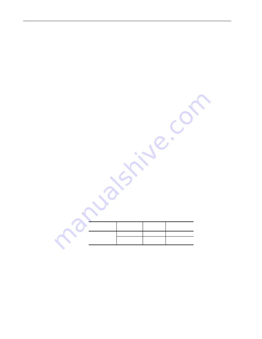
Separately ventilated motors must have the following volume of air to
adequately cool the motor unless the motor nameplate specifies a different
value.

Power Supply

Check the motor nameplate to be sure the voltage and type of power rating
is the same as that of the power source.

A code stamped on the nameplate identifies the type of power supply that
must be used to supply armature power to the motor in order to obtain the
rated nameplate output. Since the code letter has been selected in alphabetic
order of increasing magnitude of ripple current, a motor may be operated on
a power supply having a letter designation prior in the alphabet to the letter
stamped on the nameplate, with no loss in nameplate rating.

Frame

Base Speed

RPM

Air Volume

CFM

Static Pressure

Inches of Water

DC180ATZ,
C180ATZ and
DC210ATZ

2500

152

2.0

1750 and lower

105

0.95

Summary of Contents for Allen-Bradley C180ATZ

Page 1: ...Installation Operation and Maintenance Manual DC Motors Frames DC180ATZ C180ATZ and DC210ATZ ...

Page 2: ...ght bill or express receipt If any concealed loss or damage is discovered later notify your freight or express agent at once and request him to make an inspection We are willing to assist you in collecting claims for loss or damage in shipment however this willingness on our part does not remove the transportation company s responsibility in reimbursing you for collection of claims or replacement ...

Page 3: ...matched com Installation DC motors have characteristics which can cause serious or fatal injury unless they are selected installed maintained and operated by qualified personnel familiar with special requirements of DC machines Allen Bradley DC motors are designed and built in accordance with Safety Standard for Construction and Guide for Selection Installation and Use Of Electric Motors And Gener...

Page 4: ... be lower than 0 degrees C to provide base speed and regulation within NEMA limits Use of outside air below 0 degrees C may cause excessive brush and commutator wear due to the low humidity Cooling air absolute humidity must be at least 2 grains per cu ft Important Motors located in damp moist environment must have space heater or fields energized at 50 voltage to protect against condensation when...

Page 5: ... quantities may be omitted from the code If one of the quantities is indicated both must be included to avoid confusion Conduit Box Conduit boxes can be rotated in 90 degree increments for lead outlet at top sides or bottom Conduit box locations can be changed from F1 to F2 or F2 to F1 by rotating the commutator end bracket 180 degrees and reconnecting the leads The conduit box location cannot be ...

Page 6: ...rmostats leads marked P1 P2 etc designed to trip before the frame reaches the maximum allowable temperature for specific class and group The normally closed contacts of the thermostat must be connected in that motor control circuit so that power to the motor armature and field is removed immediately when the thermostat trips An explosion proof tachometer mounted on the motor will also have an inte...

Page 7: ... caps can be rotated either 90 or 180 degrees to conveniently locate grease fittings or air outlet openings Handhole covers can be interchanged as necessary Important Vertical mount drip covers are required to provide protection to vertically mounted Drip Proof motors Stock motors and other motors designed for horizontal mounting can be adapted for vertical mounting by ordering vertical mount drip...

Page 8: ...djusted as required for proper operation The belt sheaves should be placed as close as possible to the motor bracket Shipping Blocks Motors supplied with roller bearings at the drive end are shipped with wooden blocking to prevent axial movement of the shaft during shipment Remove the blocking and bolts securing it and discard Make sure motor shafts turn freely If motor is to be reshipped blocking...

Page 9: ... On Motor Shafts To avoid excessive bearing loads and shaft stresses belts should not be tightened more than necessary to transmit the rated torque The pre tensioning of the V belt drive should be based on the total tightening force required to transmit the horsepower divided by the number of belts This procedure avoids the excessive load caused by tightening individual belts to a prescribed level...

Page 10: ...d minus for loads acting downward with gravity Drive Multiplier Flat Belt See Note 1 1 33 Timing Belt See Note 2 0 9 Chain Sprocket 0 7 Spur Gear 0 75 Helical Gear 0 85 ATTENTION The use of these radial load capacities requires the accurate calculation of the radial load for the application Radial loads for gears sprockets and flywheel are usually accurately determined but the radial loads due to ...

Page 11: ...sed on frame size Ra La WK2 τe This will provide approximate results with a 25 margin of error The following data can be derived La La x Va rpm 2 Arm Circ Ind millihenries Ra Ra x Va rpm 2 Arm Circ Resistance τe τe τe La Ra x 103 Elec Time Constant J SEC WK2 x rpm 2 1 62 x 10 6 x hp where WK2 is in terms of lb ft2 J SEC WK2 x rpm 2 0 0922 x 10 6 x kw where WK2 is in terms of kg m2 R Ia x Ra Va IaR...

Page 12: ...To guard against personal injury and or machine damage observe the following precautions before initial start up Remove all unused shaft keys and loose rotating parts to prevent them from flying off Replace covers and protective devices Verify that all separately excited fields are excited at their rated voltage and that relative polarities of all fields are correct See Checking Relative Polarity ...

Page 13: ...sure blower is running in proper direction While operating the motor observe the performance It should run smoothly with little noise The bearings should not overheat and should reach a leveling off temperature Any undue noise overheating sparking or erratic performance should be investigated and necessary corrective action taken immediately to prevent serious damage Before attempting any repairs ...

Page 14: ...of unstable performance of shunt wound DC motors is incorrect series field polarity relative to the shunt field due to improper connection Relative polarity of the shunt and series fields can be checked as follows 1 Connect a low scale 3 volt DC voltmeter across the shunt field terminals F1 F2 with F1 connected to the positive terminal of the meter At least one of the shunt field leads must be dis...

Page 15: ...t and the available armature terminal for the test For example use S 2 and A l if S 1 and A 2 arc connected together at the motor and not brought to the controller Maintenance Inspections Regular inspection at intervals dependent upon service conditions is the best insurance against costly maintenance and breakdown Experience is the best guide Record inspection results and maintenance action requi...

Page 16: ...e basis of the most severe operating parameter i e temperature bearing load atmosphere or operating hours per day Table I Service Condition 1 Motors must be specially designed for operation in ambient outside the range of 30 to 40 degrees C 22 to 104 degrees F Special grease is required 2 Extreme service conditions are rare in actual practice Corresponding lubrication cycles should therefore be ap...

Page 17: ...otors do not have a grease drain plug but have a grease relief around the grease inlet pipe Frames C180ATZ on commutator end opposite drive end All C Face and D Flange frames on drive end 4 Using a manual grease gun pump in the recommended grease in the amount shown in Table H This amount of grease will provide an ample supply of lubricant between lubrication periods as determined from Table J for...

Page 18: ...ute grease within bearings before starting motor Bearings These motors are designed to provide a mounting for anti friction bearings to give Maximum protection to windings and interior of machine by preventing grease leakage from bearing housing Maximum protection to bearings against excess lubricant insufficient lubricant dirt and moisture Various types of anti friction bearings are used in the w...

Page 19: ...ld have sleeved pigtails Commutator A commutator in good condition is clean and smooth with a medium polish and a light brown color Keep clean by occasionally wiping with a canvas pad Use no lubricant or emery abrasive If a commutator becomes rough it needs to be resurfaced Roughness can be easily detected with the machine running by resting a pencil like rod of insulating material dry wood on one...

Page 20: ...tor 4 Streaking or threading of commutator surface Rough commutator with associated sparking Fine lines in brush track 1 Low average current density in brushes due to light machine loading 2 Contaminated atmosphere 3 Oil on commutator or oil mist in air 4 Humidity too low 5 Lack of film forming properties in brush 6 Brush too abrasive 5 Bar etching or burning Rough commutator with associated spark...

Page 21: ...ning with water 5 After heavy cleaning spray with a very light coat of protective oil to protect against possible loss of plating Important Do Not use flammable solvents to clean filters Important Standard washable filters may not be suitable for motors operating in atmospheres with heavy concentrations of oil mist Oil mist may be drawn into the motor and cause damage to the commutator and winding...

Page 22: ... are standard construction details for the various frames DC180ATZ DC210ATAZ Drive end bearing fits in a machined cavity in the bracket with inner cap Commutator end bearing has single seal on side facing commutator C180ATZ Bearings fit in a machined cavity in the end brackets Inner caps are used Bearing Replacement Remove bearing by means of bearing puller Clean bearing housing and bearing seat p...

Page 23: ...d on the side C180ATZ Conduit box is located on the commutator end bracket Parts Identification C180AT DC180ATZ DC210ATZ Number Description Number Description 1 Grease Plug C180 only FE 12 Inner Coil 2 Grease Plug C180 only BE 13 Armature Core 3 Ball Bearing FE 14 Frame 4 Ball Bearing BE 15 Armature Coil 5 Rocker 16 Inner Fan 6 Bracket FE 17 Key 7 Bracket BE 18 Shaft 8 Brush 19 Conduit Box 9 Brush...

Page 24: ...ained from the Allen Bradley Drives Motors home page on the World Wide Web at http www controlmatched com Publication 1325L UM001B EN P August 2001 Supersedes 1325L UM001A EN P dated May 2001 Copyright 2001 Rockwell Automation All rights reserved Printed in USA ...

Reviews: